What Transportation Equipment Plants Actually Discharge
A typical US transportation equipment plant — auto tier-one, rail car, truck driveline, or aerospace component shop — runs six wastewater streams that converge at the pretreatment headworks: parts-washer overflow, vibratory finisher discharge, machining coolant blowdown, phosphate/nitrite conversion-coating rinse water, oily condensate from compressed-air systems, and general floor wash. The combined signature is identifiable and rough on a BOD/COD meter: COD 1,500–8,000 mg/L, O&G 200–5,000 mg/L, TSS 500–3,000 mg/L, dissolved metals (Zn, Cu, Cr, Pb) 5–100 mg/L, and pH that swings 3–11 across shifts (HydropureWater field data, 2025–2026). The streams defeat simple gravity separation because semi-synthetic coolants and drawing compounds carry sulfonated emulsifiers and extreme-pressure additives that hold oil droplets below 20 µm in stable suspension. That is why the EPA NPDES framework page (S2, EPA — municipal wastewater) is necessary but not sufficient: it names the permit authority, not the chemistry on your floor.
Regulatory Framework: NPDES, POTW, and 40 CFR 433
The US pretreatment system is a three-layer pyramid. At the top, the EPA's NPDES program sets the permitting umbrella (S2, EPA). Under it, a Publicly Owned Treatment Works (POTW) runs its own pretreatment program, enforces local limits through a control authority, and passes industrial flow to the head of its biological plant. At the base, federal categorical standards under 40 CFR Part 403 force "categorical industrial users" to meet technology-based numbers regardless of what the local POTW allows. For metal-finishing lines, that category is 40 CFR 433, whose daily maximums are the binding targets: O&G 100 mg/L, total toxic organics 2.13 mg/L, total toxic metals 4.1 mg/L, lead 0.6 mg/L, cadmium 1.2 mg/L, total chromium 4.0 mg/L, copper 4.0 mg/L, nickel 4.0 mg/L, zinc 4.0 mg/L.
Local POTW limits are typically tighter than the categorical floor. A defensible envelope based on US automotive and aerospace POTW discharge permits (2024–2026 reviews): pH 5.0–10.0 (instantaneous), TSS 250–600 mg/L, ammonia 20–50 mg/L as N, O&G 100–200 mg/L, COD 300–600 mg/L. The POTW also has a structural reason to be strict: sanitary sewer overflows (SSOs) and inflow/infiltration (I&I) reduce plant capacity (S2, EPA), so a slug load from your equalization basin pushes their biological train past its nitrification window in a single shift. Equalization is not optional — it is the contract that lets you discharge at all.
| Regulatory Layer | Authority | Key Limit (daily max) | Source |
|---|---|---|---|
| Federal categorical | 40 CFR 433 (Metal Finishing) | O&G 100 mg/L; total metals 4.1 mg/L; Pb 0.6 mg/L; Cd 1.2 mg/L; Cr/Cu/Ni/Zn 4.0 mg/L each | EPA |
| Federal categorical | 40 CFR 433 (Metal Finishing) | Total toxic organics 2.13 mg/L | EPA |
| Local POTW (typical envelope) | POTW control authority | pH 5.0–10.0; TSS 250–600 mg/L; NH₃-N 20–50 mg/L; O&G 100–200 mg/L; COD 300–600 mg/L | 2024–2026 POTW permits |
| Permit umbrella | EPA NPDES | Defines municipal discharge framework | S2, EPA |
The Standard Pretreatment Process Train
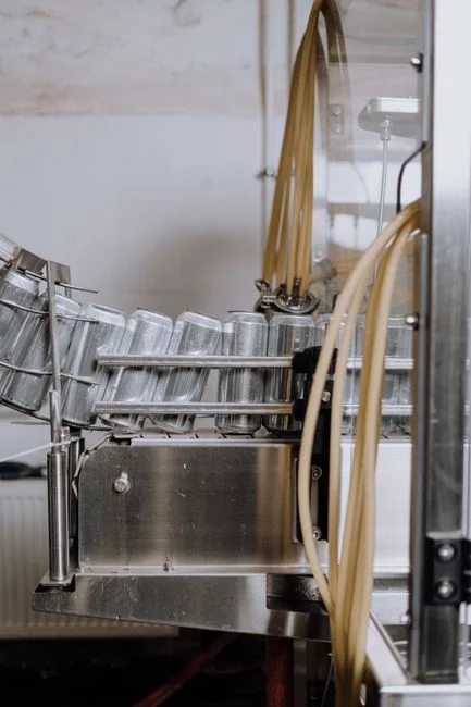
Step 1 — a rotary mechanical bar screen with 1–3 mm openings strips rags, plastic dunnage, and stringy coolant debris before they foul DAF pumps and coat lamella plates. Step 2 — an equalization basin sized at 8–24 hours of peak flow with submersible mixers damps pH and O&G swings; design HRT is typically 12 h, and the basin doubles as a buffer against SSO-triggering slug loads at the receiving POTW (S2, EPA). Step 3 — an industrial DAF system operating at 4–25 m/h hydraulic loading and 4–6 g/L air-to-solids ratio targets 85–95% O&G and 80–90% TSS removal, breaking the coolant emulsion that gravity oil/water separators cannot (see the sizing logic in How to Size a DAF for Compressor Oily Condensate: 2026 Engineering Guide). Step 4 — pH adjustment to 8.5–9.5 with sodium hydroxide through an automatic chemical dosing system, followed by hydroxide precipitation of dissolved metals using ferric chloride or lime as coagulant. Step 5 — a lamella clarifier (plate pack) operating at 20–40 m/h surface loading settles the precipitated metal-hydroxide sludge. Step 6 — optional biological polishing (MBBR or MBR) reduces COD and ammonia when the local POTW limit is <30 mg/L NH₃-N; the operating envelope is detailed in MBR Wastewater Treatment System Working Principle: 2026 Engineering Specs. Step 7 — effluent pH trim to 6.5–8.5 with continuous online monitoring before discharge to the sanitary sewer.
| Step | Unit Operation | Design Parameter | Target Removal / Output | Limit Protected |
|---|---|---|---|---|
| 1 | Rotary mechanical bar screen | 1–3 mm opening | Rags, debris removal | Protects downstream DAF |
| 2 | Equalization basin | 8–24 h HRT, 12 h typical; submersible mixers | pH/COD/O&G dampening | POTW slug-load tolerance |
| 3 | DAF unit | 4–25 m/h; 4–6 g/L A/S ratio | 85–95% O&G; 80–90% TSS | 40 CFR 433 O&G 100 mg/L |
| 4 | pH adjust + chemical precipitation | pH 8.5–9.5; NaOH, FeCl₃ or lime | Dissolved metals to hydroxide form | 40 CFR 433 metals 4.1 mg/L |
| 5 | Lamella clarifier | 20–40 m/h surface loading | Metal-hydroxide sludge separation | Local POTW TSS 250–600 mg/L |
| 6 | Biological polishing (MBBR/MBR) | MBR flux 12–18 L/m²·h; MLSS 8,000–12,000 mg/L | COD <250 mg/L; NH₃-N <10 mg/L | Local POTW COD/NH₃ |
| 7 | Effluent pH trim + monitoring | pH 6.5–8.5; continuous probe | Compliant discharge | POTW pH 5.0–10.0 |
Matching Each Unit Operation to the Pollutant It Removes
Every piece of equipment in the train answers a specific "why is this here" question from the regulator. The table below pairs each pollutant of concern at a transportation equipment plant with the unit operation that strips it, the typical influent and effluent envelope, and the standard it is designed to hit. Zinc and trivalent chromium are the two metals that most often drive 40 CFR 433 excursions at tier-one parts plants, because both dissolve in conversion-coating rinses and ride out of the DAF in soluble form unless pH is pushed into the hydroxide window.
| Pollutant | Pretreatment Unit | Typical Influent | Typical Effluent | Standard Hit | Notes |
|---|---|---|---|---|---|
| O&G (emulsified) | DAF with coagulant break | 1,000 mg/L | ≤50 mg/L | 40 CFR 433 = 100 mg/L | Emulsion must be broken before flotation |
| Zinc (dissolved) | pH 9.0 + hydroxide precipitation | 20 mg/L | <2 mg/L | 40 CFR 433 = 4.0 mg/L | Lowest solubility at pH 9.0–9.5 |
| Trivalent chromium | pH 8.5 + ferric coagulant | 10 mg/L | <1 mg/L | 40 CFR 433 = 4.0 mg/L | Cr(VI) must be reduced first; see Cr(VI) handling below |
| Coolant (COD) | DAF + biological (if required) | 5,000 mg/L COD | <250 mg/L | Local POTW COD 300–600 mg/L | DAF alone meets ≥600 mg/L POTW limits |
| Ammonia (amine coolants) | MBR or MBBR nitrification | 30 mg/L NH₃-N | <10 mg/L | Local POTW limit | Required only if POTW sets NH₃-N cap |
| TSS (post-precipitation) | Lamella clarifier | 400 mg/L | <30 mg/L | Local POTW TSS 250–600 mg/L | Plate-pack surface loading 20–40 m/h |
Handling and Dewatering the Sludge Side
A pretreatment system without a closed sludge mass balance is not a pretreatment system — it is a transfer of liability. DAF skimmings run 1–3% of the influent flow, and metal-hydroxide sludge from chemical precipitation adds another 4–8 kg of dry solids per cubic meter treated (HydropureWater field data, 2025–2026). A plate-and-frame filter press operated at 6–10 bar feed pressure targets 25–35% dry solids, which is the envelope most US municipal solid-waste landfills accept without a paint-filter liquids test failure. For manifests, DAF skimmings from petroleum-bearing coolants typically carry waste code F037, and metal-hydroxide sludge from conversion-coating lines is commonly classified F006 (electroplating) — confirm both against 40 CFR 261 and your state generator rules before the first manifest is signed. Filtrate from the press is normally recycled to the head of the equalization basin; this loop is why the equalization tank design HRT must include filtrate return flow, not just fresh plant discharge.
When to Add a Biological or Membrane Step
Biological polishing is the most expensive add-on in the train, and it is not always required. Use this decision framework:
- Skip biological if the POTW COD limit is ≥600 mg/L and there is no ammonia cap. DAF + precipitation alone delivers a compliant discharge for the majority of single-shift tier-one parts plants in this envelope (HydropureWater field data, 2025–2026).
- Choose MBBR when the plant runs one shift, flow is <200 m³/day, and ammonia is the only polishing target. MBBR is capital-friendly, has no membrane to foul, and tolerates the 3–11 pH swings that equalization cannot fully dampen.
- Choose MBR when the plant needs water reuse for rinse lines, or runs >2 shifts with ammonia load >20 mg/L, or faces a total nitrogen cap. Specify submerged PVDF modules at 0.1–0.4 µm pore size, design flux 12–18 L/m²·h, MLSS 8,000–12,000 mg/L; the resulting footprint is roughly 60% of a conventional activated-sludge + clarifier train. The full operating envelope is laid out in MBR Wastewater Treatment System Working Principle: 2026 Engineering Specs.
For hexavalent chromium specifically — when a coating line discharges Cr(VI) — reduce to Cr(III) with sodium bisulfite at pH 2–3 before the precipitation step, then raise pH to 8.5 for hydroxide removal. The electrochemical alternative is covered in Electrocoagulation for Chromium Removal: 2026 Engineering Specs.
Frequently Asked Questions
What is the federal O&G limit for metal-finishing plants discharging to a POTW?
The federal daily maximum is 100 mg/L oil and grease under 40 CFR 433.11 (Metal Finishing categorical standard), with most local POTWs tightening this to 100–200 mg/L in their control authority ordinances.
Can a transportation parts plant use only an oil/water separator?
No. Semi-synthetic coolants and drawing compounds carry sulfonated emulsifiers that hold oil droplets below 20 µm in stable suspension; gravity API or CPI separators recover free oil only. A DAF unit with coagulant break is required to break the emulsion and float the dispersed phase.
How is hexavalent chromium handled if it is present?
Reduce Cr(VI) to Cr(III) with sodium bisulfite at pH 2–3 in a dedicated reduction tank, then raise pH to 8.5 with sodium hydroxide to precipitate chromium hydroxide alongside the other dissolved metals.
What is the typical hydraulic residence time for the equalization basin?
Design for 8–24 hours of peak flow, with 12 hours as a typical engineering target. This range dampens pH, O&G, and COD swings enough to keep slug loads from triggering sanitary sewer overflows at the receiving POTW.
How often must a categorical industrial user self-monitor?
At minimum once per quarter, per 40 CFR 403.12(b) baseline monitoring requirements. The POTW control authority may impose more frequent sampling — often monthly for O&G and metals — and the categorical user must report all results in the annual report due by a date set in the control mechanism.
Related Equipment
- MBR system — specifications, capacity range, and technical data