Why Soapstock Water Breaks Generic ZLD Designs
Sizing a ZLD system for edible oil soapstock water starts with characterizing the combined acid-oil, wash, and floor-spillage streams — typically 50–90 °C, COD 20,000–80,000 mg/L, FOG 2,000–15,000 mg/L — then sequences DAF or API oil removal, equalization, pH/temperature conditioning, biological reduction (MBR), RO concentration at 50–70% recovery, and MVR evaporation plus crystallization to reach >95% overall water recovery with zero liquid discharge. The train is a closed-loop build-out, not a single piece of hardware: a soapstock ZLD that treats the brine stream as the "hard part" while glossing over FOG destruction upstream will foul membranes in weeks and never reach the evaporator duty the CAPEX request assumed.
Soapstock water is the combined discharge from acidulation of caustic-refining soapstock, refinery wash water, and floor or equipment spillage, typically leaving the refinery at pH 1–4 and 50–90 °C. The defining feature is emulsified FOG at 2,000–15,000 mg/L together with sulfated and saponified organics that defeat standard coagulation chemistry. As Mohan (STAI Annual Convention, 2024-07) frames water management in a closed loop, the correct mental model is reduce–reuse–recycle–respect, with ZLD as the final step in that hierarchy rather than a substitute for it (doi.org/10.69794/82sac/978-81-969264-0-3/241-246). Applied to a refinery, that means FOG recovery in the DAF, water reuse from the RO and MVR condensate, and salt/solid handling only on the residue.
The MDPI 2025 review of membrane technologies in ZLD/MLD systems reinforces the same point: membranes are one component in an integrated train, not a standalone solution, and they fail predictably when feedwater carries emulsified oil, sulfate, or silica past the pretreatment envelope (Panagopoulos & Michailidis, 2025-02, doi.org/10.3390/membranes15020064). For soapstock water that means the RO stage can only be designed after a robust FOG and COD destruction step — a sizing decision, not an operational tweak.
Step 1 — Characterize the Combined Soapstock Stream
Defensible ZLD sizing starts with a 7-day composite sampling campaign that covers production peaks (deodorizer bleed, batch acidulation) and weekend low-flow periods. Under-sampling the peaks is the single most common reason an installed ZLD runs out of hydraulic capacity within 12 months of startup. The design flow should be set at 1.2–1.3× the average measured flow to absorb shift discharges without exceeding downstream rating.
Send samples to a commercial lab for COD, BOD₅, FOG (hexane extractable), TSS, VSS, sulfate, chloride, total phosphorus, conductivity, and a temperature profile across the day. The table below lists the typical envelope a refinery engineer should expect for combined soapstock water before any treatment, drawn from published refinery wastewater characterizations and HydropureWater field data on edible-oil processing streams (2025–2026).
| Parameter | Typical range | Design implication |
|---|---|---|
| COD | 20,000–80,000 mg/L | Sets biological loading and MBR sizing |
| BOD/COD ratio | 0.35–0.55 | Stream is biodegradable but slowly |
| FOG (hexane extractable) | 2,000–15,000 mg/L | Drives DAF sizing and antifoam strategy |
| TSS | 500–3,000 mg/L | Determines equalization and screening |
| Sulfate (SO₄²⁻) | 1,000–5,000 mg/L | Limits RO recovery to ~70% per pass |
| TKN | 200–800 mg/L | Defines nutrient dosing for MBR |
| Temperature | 50–90 °C | Forces cooling before biological step |
| pH | 1–4 | Requires neutralization before MBR |
Once the envelope is in hand, the rest of the train sizes against these numbers rather than against a textbook profile. The biggest source of field under-performance is a sulfate number taken on a single weekday grab that misses the acidulation batch.
Step 2 — Pretreatment: Oil, Solids, and Temperature Control
DAF is the first FOG removal step and the single most important unit for protecting every downstream stage. Sized at 4–300 m³/h and operated at 15–25 m/h surface loading, a properly configured HydropureWater DAF for FOG removal pulls free and emulsified oil down to 100–200 mg/L — the threshold below which an MBR can hold steady flux. Without that step, free and emulsified oil smothers biomass and causes MBR fouling within weeks, and no antiscalant program downstream will save the RO.
Equalization follows the DAF and is sized for an HRT of 8–12 h to dampen 60–90 °C peaks from batch acidulation. Cooling — a plate heat exchanger sized for 200–250 kW per 100 m³/day, or a forced-draft cooling tower where water is scarce — brings the stream to <40 °C for the biological step. Fine screening at 1–3 mm sits ahead of the MBR tank to keep rags and solidified fat from reaching the membranes. A PLC-controlled coagulant and pH dosing skid handles coagulant (typically 50–150 mg/L PAC or polyaluminum chloride) and pH correction to 6.5–7.5, which is the operating window the MBR biology needs.
Engineers new to the train should read the companion soapstock-before-MBR pretreatment guide before locking in chemistry; acidulation wash water behaves differently from generic refinery wastewater and the coagulant dose window is narrower than most textbooks suggest (HydropureWater field data, 2025-08).
Step 3 — Biological Reduction and MBR Polishing
The MBR has one job: drop COD to 200–500 mg/L, BOD to <20 mg/L, and FOG to <50 mg/L so the RO can run at design recovery without accelerated cleaning. Anything above that envelope compresses RO recovery, multiplies CIP frequency, and pushes the evaporator into a duty range that no MVR is sized for. Size the MBR for an F/M of 0.10–0.20 kg BOD/kg MLVSS·d and an HRT of 18–30 h. The HydropureWater MBR for high-COD refinery effluent range of 10–2,000 m³/day brackets most soapstock applications.
Refinery streams often need FOG-tolerant biology — acclimated activated sludge, or a sequencing batch reactor staged ahead of the MBR — because emulsified oil that survives the DAF will pass through a non-acclimated biomass and foul the membranes within a few weeks of steady-state operation. The MBR stage is also where the engineer commits to a discharge envelope; downstream sizing is no longer forgiving if MBR effluent drifts above target. For pretreatment details that protect this step, the companion soapstock-before-MBR pretreatment guide covers the chemistry in more depth.
As a cross-check against other closed-loop sizing problems, the sibling ZLD sizing guide for e-coat UF reject applies the same F/M and HRT logic to a different feed but reaches the same conclusion: the membrane stage only performs if the upstream biology holds its design envelope.
Step 4 — Membrane Concentration: RO and Brine Volume Reduction
Per the MDPI 2025 review of membrane technologies in ZLD/MLD systems, the membrane stage is the workhorse of any modern closed-loop design (Panagopoulos & Michailidis, 2025-02, doi.org/10.3390/membranes15020064). In a soapstock ZLD it typically recovers 50–70% of the MBR permeate as product water and sends 30–50% forward as RO brine to the evaporator. The table below summarizes the operating envelope an engineer should target for a single-pass RO on soapstock permeate, with values consistent with membrane manufacturer datasheets and refinery field installations (HydropureWater field data, 2025–2026).
| Parameter | Target range | Comment |
|---|---|---|
| Pump pressure | 70–80% of clean-water rating | Limits compaction and energy draw |
| Recovery per pass | 50–70% | Higher recovery hits sulfate scaling |
| Flux at 25 °C | 10–18 LMH | Drop to 8–12 LMH at 35 °C feed |
| Antiscalant dose | 2–5 mg/L | Targets sulfate and silica scaling |
| Feed pH | 6.5–7.5 | Matches MBR effluent window |
| Brine TDS | 30,000–60,000 mg/L | Sets MVR duty downstream |
Pushing single-pass recovery past ~70% converts sulfate and silica scaling into a cleaning-cycle problem — flux holds for a few weeks, then collapses and the membrane stack has to be cleaned twice as often. For plants targeting >85% water recovery before the thermal step, use a two-pass RO with the second pass on the first-pass concentrate, or an RO + nanofiltration / forward-osmosis hybrid. A multi-media filter for RO feed protection at 5–10 µm absolute sits ahead of the high-pressure pump to keep particulates off the membrane surface, and the industrial RO rated up to 95% recovery frames the upper bound for two-pass designs. For a closer look at high-recovery RO configurations, see the RO configuration options for high-recovery reuse guide.
Step 5 — Thermal Polishing: MVR Evaporator Sizing
MVR (mechanical vapor recompression) is the default evaporator for soapstock brine because it cuts specific energy consumption to 20–35 kWh/m³ of evaporated water, against 80–120 kWh/m³ for a multi-effect evaporator on the same feed. MVR condensate typically returns at conductivity <50 µS/cm, which is clean enough to recycle back to refinery service water or to feed the boiler makeup train. For a CAPEX-grade sizing, use the rule of thumb of 0.13–0.18 m² of evaporator heat-transfer area per m³/day of brine feed, with residence time 0.5–1.0 h to reach 60–70% w/w total dissolved solids in the concentrate leaving the evaporator.
The vapor side of the design is what catches first-time specifiers. Use titanium or duplex heat-exchange surfaces to handle the chloride and sulfate load at boiling temperature, allow 6–10 °C of boiling-point elevation (BPE) for the 60–70% TDS concentrate, and size non-condensable gas venting to roughly 0.5–1.0% of the recompressor throughput to keep the vapor side from blanketing. Recompressor electrical load scales directly with evaporated water: at 30 kWh/m³ and 8,000 operating hours per year, a 27 m³/day brine feed draws about 270 kW continuous.
For very small plants — under 20 m³/day of RO brine — a skid-mounted thermal evaporator with a finned-tube heat exchanger is often cheaper than a full MVR train, even though specific energy is higher. Set the threshold at the point where recompressor CAPEX is recovered against operating cost, which on current Chinese-built MVR skids lands in the 15–25 m³/day brine range (HydropureWater field data, 2025-11).
Step 6 — Crystallization, Solid Handling, and the Zero-Discharge Mass Balance
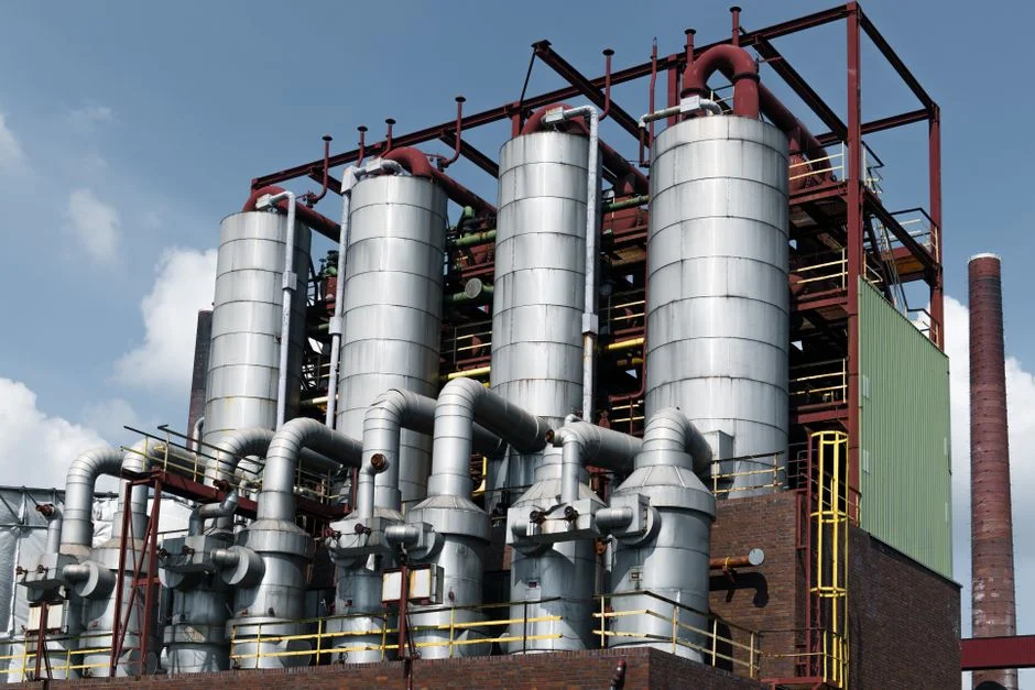
The 60–70% TDS concentrate leaving the MVR goes to a forced-circulation crystallizer or an agitated thin-film dryer to push moisture below 5–10% so the residue can be handled as a solid rather than a slurry. Size the crystallizer for a residue of 3–8% of the original raw-soapstock feed volume — for a 100 m³/day plant that is 3–8 m³/day of wet salt and organic cake. The split between inorganic salt and organic-rich cake depends on how much sulfate the upstream acidulation step contributes; sulfate-rich cake usually routes to a lined industrial landfill, while organic-rich cake can go to a licensed waste-to-energy facility if the chloride loading stays below the combustor's specification.
A filter press for crystallizer cake dewatering ahead of the disposal step takes the wet cake from 60–80% moisture down to 25–35%, which cuts hauling weight roughly in half. A high-efficiency sedimentation tank upstream of the filter press captures any suspended fines that escape the crystallizer and recycles them back to the evaporator. The mass balance closes at 95–98% overall water recovery, with the residual 2–5% leaving the battery limits as solids — which is what satisfies the ZLD definition in a CAPEX defense. The table below lays out where each stream sits on a normalized 100 m³/day basis.
| Stream | Flow (% of feed) | Recovery / fate |
|---|---|---|
| Raw soapstock water | 100% | Feed to DAF |
| DAF effluent | ~95% | Forward to equalization |
| MBR permeate | ~90% | Forward to RO |
| RO permeate (reused) | ~63% | Reused in refinery |
| MVR distillate (reused) | ~25.5% | Reused in refinery |
| Crystallizer cake (solid) | 0.6–0.8% | Landfill or waste-to-energy |
Worked Example: Sizing a ZLD Train for 100 m³/day of Soapstock Water
Take a 100 m³/day combined soapstock stream at 70 °C, COD 45,000 mg/L, FOG 6,000 mg/L, sulfate 2,500 mg/L. The DAF (4–300 m³/h capacity) cuts FOG to ~150 mg/L with 5% water loss to skimmings, leaving 95 m³/day for equalization. The equalization basin and cooling loop hold the stream at <40 °C for the MBR (10–2,000 m³/day capacity range), which produces 90 m³/day of permeate at COD ~400 mg/L and FOG <50 mg/L.
RO at 70% recovery produces 63 m³/day of permeate for reuse and 27 m³/day of RO brine at 30,000–45,000 mg/L TDS. The 27 m³/day RO brine feeds an MVR sized at 0.16 m²/m³/day — roughly 4.3 m² of heat-transfer area — which returns 25.5 m³/day of distillate at <50 µS/cm for reuse and produces 1.5 m³/day of 65% TDS concentrate. That concentrate drops to a forced-circulation crystallizer, which yields 0.6–0.8 m³/day of salt/organic cake to a filter press for crystallizer cake dewatering and onward disposal.
Total water recovery is ~96%, with 0.6–0.8 m³/day of solids leaving the battery limits. The equipment map lines up against the HydropureWater DAF for FOG removal, the HydropureWater MBR for high-COD refinery effluent, and the industrial RO rated up to 95% recovery — concrete numbers the engineer can present in a CAPEX meeting. The table below compresses the calculation.
| Stage | Feed (m³/day) | Product / reuse (m³/day) | Residue (m³/day) |
|---|---|---|---|
| DAF | 100 | 95 | 5 (skimmings) |
| Equalization + cooling | 95 | 95 | 0 |
| MBR | 95 | 90 (permeate) | 5 (waste sludge) |
| RO (70% recovery) | 90 | 63 (permeate) | 27 (brine) |
| MVR | 27 | 25.5 (distillate) | 1.5 (65% TDS) |
| Crystallizer + filter press | 1.5 | 0 (solid cake) | 0.6–0.8 |
Frequently Asked Questions
What overall water recovery should I plan for on a soapstock ZLD?
Plan for 95–98% overall water recovery across the full train, with 63% coming from the RO at 70% single-pass recovery and another 25–26% from the MVR distillate. The residual 2–5% leaves the battery limits as crystallizer cake, which is what qualifies the system as ZLD rather than MLD.
How much electrical energy does the MVR evaporator draw on soapstock brine?
Expect 20–35 kWh per cubic meter of evaporated water, which on a 27 m³/day RO brine feed at 30 kWh/m³ and 8,000 operating hours per year works out to about 270 kW of continuous recompressor load. That is roughly one-third the energy a multi-effect evaporator would draw on the same duty.
What do I do with the salt/organic cake from the crystallizer?
Route sulfate-rich cake to a lined industrial landfill and send organic-rich cake (low chloride, mostly sodium salts of fatty acids) to a licensed waste-to-energy facility, provided chloride stays below the combustor's specification. Dewater the cake with a filter press to 25–35% moisture before hauling.
What is the smallest feed flow at which a full ZLD is still economic?
For a soapstock stream, full ZLD becomes economic at roughly 50 m³/day of combined feed. Below 20 m³/day of RO brine (about 60–70 m³/day of raw feed), a skid-mounted thermal evaporator usually beats a full MVR train on CAPEX, even though the specific energy is higher. The 100 m³/day worked example sits comfortably above the threshold.
How should I handle a high-sulfate brine that is threatening RO scaling?
Cap single-pass RO recovery at 65–70% to keep sulfate below the saturation index, dose 2–5 mg/L of a sulfate-tolerant antiscalant, and send the resulting 27 m³/day brine to the MVR where sulfate ends up in the crystallizer cake rather than on the membrane surface. Pushing past 70% recovery converts a manageable scaling risk into a weekly cleaning cycle.