
What a Dairy Whey Stream Puts on the DAF
A mid-sized cheese plant discharging 50 m³/h of whey-bearing effluent to its pretreatment screens is not sending a generic food-industry wastewater — it is sending a colloidal protein system that defeats gravity settling and demands air flotation. Dairy processing generates three distinct whey-bearing streams that the dissolved air flotation (DAF) unit must be sized to handle either blended or segregated: cheese whey (high in lactose and soluble protein, BOD 30,000–60,000 mg/L if unconcentrated), whey permeate from ultrafiltration (lower BOD but still protein- and lactose-bearing), and clean-in-place (CIP) rinse water (dilute, intermittent, surfactant-bearing, pH 2–12 across the cycle). Each stream on its own is a design problem; the blended daily composite is what the DAF actually sees.
Per the ScienceDirect dairy DAF study, dairy wastewater is characterized by high biochemical oxygen demand, high chemical oxygen demand, high dissolved solids, suspended solids, oils and greases, and nutrients such as ammonia and phosphates (S3). The envelope that the rest of this article uses to size equipment is the blended factory discharge, not the worst-case whey stream alone: flow 4–80 m³/h, COD 2,000–10,000 mg/L, TSS 500–3,000 mg/L, FOG 100–800 mg/L, pH 4–11 depending on CIP cycle phase. A reader who has only bench data on raw cheese whey should dilute those numbers by the plant's whey-to-total-flow ratio before plugging them into the four sizing equations below.
Whey protein — primarily β-lactoglobulin with residual casein fines — is the design-limiting species. These colloids carry a net negative surface charge at neutral pH, repel one another, and stay in suspension indefinitely. A conventional primary clarifier removes 10–20% of the incoming TSS from this stream; a properly conditioned DAF removes 70–90%. That delta is the entire reason DAF exists as the workhorse unit operation upstream of biological treatment in dairy plants.
| Parameter | Cheese whey (raw) | Whey permeate | CIP rinse | Blended factory envelope |
|---|---|---|---|---|
| Flow (m³/h) | 0.5–5 | 1–10 | 2–20 (intermittent) | 4–80 |
| COD (mg/L) | 30,000–60,000 | 2,000–5,000 | 500–2,000 | 2,000–10,000 |
| TSS (mg/L) | 2,000–6,000 | 200–800 | 100–500 | 500–3,000 |
| FOG (mg/L) | 500–2,000 | 50–200 | 20–100 | 100–800 |
| pH | 4.0–5.5 | 4.5–6.5 | 2–12 (cycle-dependent) | 4–11 |
The Chemistry Step: pH and Coagulant Selection for Whey Protein Flocculation
Whey protein reaches zero net surface charge at its isoelectric point near pH 4.6, which is the operating window that destabilizes the colloidal fraction and makes the protein floatable. Below pH 4 the protein carries a net positive charge and re-stabilizes; above pH 5 the negative charge returns. For a DAF on a dairy whey stream, pH correction to 4.5–5.0 is not optional pretreatment — it is the mechanism that lets the air bubbles do their job. Sulfuric acid (H₂SO₄) or CO₂ sparging are the two workhorse acidifying agents in dairy plants; CO₂ has the advantage of leaving no anion load on the downstream biological step.
The peer-reviewed optimization work on this exact problem combined Tanfloc (a tannin-based cationic coagulant) with polyacrylamide (PAM) flocculant, with both dosages and pH statistically optimized via central composite rotatable design (CCRD), and delivered expressive pollutant reductions on real dairy wastewater (S3 abstract and highlights). The dose bands that emerge from that work and from standard dairy practice are: Tanfloc 50–300 mg/L, anionic or cationic PAM 1–5 mg/L, pH 4.5–5.0. Engineers running bench jar tests should land in those envelopes before scaling; engineers with pilot data already inside those bands can move directly to the four sizing equations in the next section.
Two practical sequencing rules matter for a factory-floor specification. First, the acid and the coagulant are dosed in a flash-mix or in-line static mixer upstream of the flocculation stage, with 2–5 minutes of flocculation residence time for the PAM to bridge the destabilized colloids. Second, biological treatment downstream prefers near-neutral pH, so the sizing workflow must include a pH re-neutralization stage after the DAF — typically NaOH dosing into a 10–15 minute residence tank before the equalization basin feeding the aeration basin. Skipping the re-neutralization step will suppress nitrification and push BOD residuals above discharge limits. The acid skid, the coagulant skid, and the re-neutralization skid should be specified together as a single automatic chemical dosing skid with one controller and one set of duty/standby pumps.
The Four Sizing Equations for a Whey-Service DAF

Four equations carry the reader from bench or pilot chemistry to a tank drawing number. They are written in the order an engineer will actually use them.
Equation 1 — Surface area. A = Qpeak / HLR, where HLR is the DAF hydraulic loading rate. For high-solids food-industry DAF duty, HLR = 5–15 m/h on the flotation tank surface. Use 5 m/h for high-FOG streams or TSS above 3,000 mg/L; use 15 m/h for dilute rinse water streams below 1,000 mg/L TSS. Worked example: 50 m³/h peak at 10 m/h HLR → 5.0 m² required surface area. This surface area is the flotation zone only; the reaction/flocculation zone upstream is sized separately at 10–20 minutes of residence.
Equation 2 — Saturator recycle ratio. R = 20–40% of forward flow. Use the lower end for low-FOG, low-protein streams; use the upper end for high-protein or high-FOG whey. Worked example: 50 m³/h × 0.30 = 15 m³/h recycle pump duty. The recycle pump head must overcome the saturator pressure plus piping losses — typically 70–80 m total dynamic head at 6 bar saturator duty.
Equation 3 — Saturator pressure. 5–7 bar is the operating band. This is the pressure range that produces the 10–100 µm micro-bubbles that attach to destabilized floc; below 4 bar the bubbles are too large and rise too fast to capture protein floc, and above 8 bar the air mass exceeds the water's dissolving capacity and the excess vents unused through the relief valve. The CRC Press chapter on floc size and density in DAF (S2) is the mechanistic justification: bubble diameter and floc density jointly govern rise rate, and 10–100 µm is the band that matches a 50–500 µm protein-tannin floc.
Equation 4 — Air-to-solids ratio. Target 0.01–0.05 g air per g TSS for protein-floc flotation. Calculate from the saturator airflow (set by recycle flow × saturation concentration at 6 bar, roughly 60 g/m³) divided by the inlet TSS load. Worked example: 50 m³/h × 0.30 recycle × 60 g/m³ = 900 g/h air; at 50 m³/h forward and 1,500 mg/L TSS = 75,000 g/h TSS load; ratio = 0.012, which sits at the low end of the band — increasing recycle to 35–40% will land it mid-band for high-protein whey service.
| Equation | Formula | Range / band | Worked value at Q = 50 m³/h |
|---|---|---|---|
| 1. Surface area | A = Q / HLR | HLR 5–15 m/h | 5.0 m² at 10 m/h HLR |
| 2. Saturator recycle | R = 0.20–0.40 × Q | 20–40% | 15 m³/h at 30% |
| 3. Saturator pressure | fixed operating point | 5–7 bar | 6 bar target |
| 4. Air-to-solids ratio | (R × Csat) / (TSS load) | 0.01–0.05 g/g | 0.012 g/g → raise recycle to 35% |
These four numbers — surface area, recycle flow, saturator pressure, and air-to-solids ratio — are the specification envelope for a dissolved air flotation system on whey service. The same calculation method is independent of manufacturer, which is why the model selection in the next-to-last section is interchangeable with any DAF that hits the same four targets.
Pretreatment and Equalization: What the DAF Sees Should Already Be Screened and Balanced
A DAF sized from the four equations above is being asked to float destabilized protein floc, not to grind up casein curd chunks and packaging fragments. A rotary mechanical bar screen with 2–3 mm openings should sit ahead of the DAF to remove rags, curd, and plastics; without it, the saturator nozzles clog, the skimmer flights jam, and the air-to-solids ratio drifts off-target within days of startup.
Equalization is the second non-negotiable upstream. A surge tank sized at 4–8 hours of average flow flattens the CIP rinse spike and the cheese-vat discharge peak that otherwise arrive at the DAF as a 3–5× peak-to-average ratio. Six hours of retention is the rule of thumb: it reduces the peak-to-average ratio to 1.3–1.5×, which is the value the HLR calculation should be based on. Sizing the DAF to peak instantaneous flow rather than the EQ-attenuated peak is the single most common reason DAF tanks are oversized in dairy plants — the tank gets built for a peak that the equalization basin was supposed to erase.
The ACS work on dissolved air flotation for nutrient recovery from anaerobically digested dairy manure (S1) places DAF downstream of biological or pre-screening steps rather than as a raw influent workhorse, which is the same architectural position it occupies in a cheese plant: equalize, screen, condition with coagulant, float, then send the float to anaerobic digestion and the underflow to the activated sludge basin.
Mapping the Sized DAF to the DAF Model Range
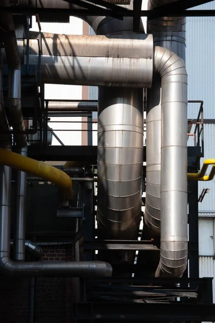
With surface area, recycle duty, saturator pressure, and air-to-solids ratio calculated, the engineer needs a purchasable model number. The DAF line covers 4–300 m³/h across 13 standard models with micro-bubble technology and automatic skimming (DAF product spec), which is the model range to map against the four flow bands that a dairy plant actually operates in.
| Flow band (m³/h) | Typical plant type | DAF model class | Notes |
|---|---|---|---|
| 4–15 | Pilot, small cheese plant, on-farm processor | Small DAF | Recycle 1–6 m³/h at 6 bar; skid-mounted |
| 15–60 | Mid-sized dairy, single cheese line | Mid DAF | Recycle 4–20 m³/h; typical 50 m³/h whey plant lands here |
| 60–150 | Butter/whey processor, multi-line dairy | Large DAF | Recycle 15–50 m³/h; often paired with dissolved air flotation in parallel trains |
| 150–300 | Centralized dairy industrial park | Largest DAF | Recycle 40–100 m³/h; multiple saturators on a common ring main |
The DAF automatic skimmer is sized for the float layer produced by the air-to-solids ratio above; protein-rich whey produces a thick, stable float that benefits from continuous skimming rather than periodic dump cycles. For a 50 m³/h plant with 1,500 mg/L TSS at 35% recycle, the expected float yield is 3–6% of forward flow as a 4–6% dry-solids cake, which the skimmer flights must remove without re-entraining the just-clarified underflow. The same HLR-based calculation method used above applies to any DAF that meets the surface area, recycle, and saturator duty, so the DAF selection is one valid commercial realization of the engineering specification rather than a unique answer to it.
Frequently Asked Questions
What hydraulic loading rate should I use for a DAF on cheese whey?
Use 5 m/h for high-FOG streams or TSS above 3,000 mg/L, and 10–15 m/h for blended factory envelopes with TSS below 1,500 mg/L. The 5 m/h lower bound is set by the rise rate of protein-tannin floc; the 15 m/h upper bound is set by the hydraulic short-circuiting that begins to drag floc out with the underflow above that rate.
Why does the pH have to be near 4.6 and not neutral?
The isoelectric point of whey protein sits near pH 4.6, where the net surface charge on β-lactoglobulin and casein is zero and the colloids agglomerate into floatable floc. At neutral pH the protein carries a net negative charge, repels other protein molecules, and stays in stable suspension; the air bubbles have nothing to attach to and the DAF underflow looks the same as the influent. The pH is re-neutralized with NaOH after flotation to protect the downstream biological step.
What saturator recycle ratio and pressure should I specify?
20–40% of forward flow at 5–7 bar saturator pressure. Use 20–25% for low-FOG, low-protein streams; use 30–40% for high-protein whey service where the air-to-solids ratio must land in the 0.02–0.04 g/g band. A 50 m³/h whey plant at 30% recycle and 6 bar requires a 15 m³/h recycle pump at roughly 75 m TDH.
How do I handle CIP rinse spikes without oversizing the DAF?
Put 4–8 hours of equalization upstream of the DAF and size the unit on the attenuated peak (typically 1.3–1.5× average flow), not on the instantaneous peak (3–5× average). Six hours of surge retention is the standard rule of thumb for dairy plants, and it is the single most effective lever for keeping the DAF tank size, recycle pump, and saturator all in the mid-range of the DAF model matrix rather than stepping up one band.