Why Diesel Generator Washdown Needs a Dedicated DAF
A standby diesel set washed down with degreaser produces a recurring, intermittent oily stream that most generic oil-in-water references fail to scope correctly. A single wash typically generates 200–1,000 L of run-off per generator; on a 1–10 m³/day wash pad the total petroleum hydrocarbons (TPH) in the bund water routinely fall inside a 200–2,000 mg/L working envelope (typical operating range, not a measured value from the source). That is two orders of magnitude above the 50 mg/L soap-oil-and-grease (SOG) discharge benchmark widely cited in industrial and municipal discharge permits (MDPI 2020, Processes 8(4):383).
A simple API oil-water separator will not carry this load. Wash-pad detergents partially emulsify the diesel fraction, so the free oil that an API separator is designed to skim becomes a stable oil-in-water emulsion that passes straight through. Dissolved air flotation (DAF) handles the emulsified fraction because it couples micro-bubble attachment with a coagulant chemistry step that breaks the emulsion first. Compared with conventional sedimentation, DAF offers rapid output, high hydraulic loading, and short residence time, all of which suit an intermittent, peak-shift flow regime (MDPI 2020, citing Edzwald). For a facility engineer sizing treatment for a remote tower site or a data-center gen-farm, the design driver is the peak shift flow, not the daily volume, and that is exactly the regime a compact DAF skid is built for.
Dissolved Air Flotation: The Configuration That Fits a 1–10 m³/d Washdown Duty
Pressure dissolved air flotation is the dominant industrial choice for oil-bearing streams because the bubble size, recycle rate, and saturator pressure can all be tuned to the influent (MDPI 2020). Dispersed-air units produce coarse bubbles (>100 µm) that lift free oil but struggle with emulsified droplets, while electrolytic cells introduce dissolved-gas species that complicate downstream chemistry. For a 1–10 m³/d generator washdown duty, pressure-DAF is the only configuration that combines a small footprint with the bubble-size control needed to lift diesel micro-droplets.
The micro-bubble mechanism is straightforward. Saturated recycle water is depressurised through a needle valve or eductor at the DAF inlet, releasing 20–80 µm bubbles that nucleate on the surface of destabilised oil droplets. The bubble-droplet aggregate has a bulk density below water and rises to the surface in the contact zone of the cell, where a mechanical scraper removes the froth. DAF was first deployed in the early 1960s for drinking-water treatment in Scandinavia, the UK, and South Africa (MDPI 2020), and the technology migrated into industrial wastewater as engineers recognised its high-rate, low-footprint profile. For a deeper walkthrough of the saturation and depressurisation mechanics, see this pressure flotation mechanics and efficiency reference.
DAF Design Parameters for Diesel Washdown: Recycle, Pressure, Bubble Size, Loading
Sizing a P&ID for a 1–10 m³/d wash pad requires defining four parameters: recycle ratio, saturation pressure, bubble size, and hydraulic loading. The table below summarises the working envelope.
| Parameter | Working envelope for diesel washdown | Design driver |
|---|---|---|
| Recycle ratio (recycle : forward flow) | 10–30% | Lower for free oil, higher for emulsified oil from detergent wash |
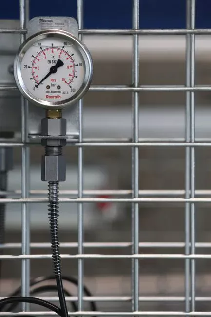
| Saturation pressure | 4–6 bar (60–90 psi) | Band that produces 20–80 µm bubbles without excessive pumping cost |
| Micro-bubble size | 20–80 µm | Match to destabilised oil droplet size; too small and rising velocity collapses, too large and attachment efficiency drops |
| Hydraulic loading rate | 5–25 m/h | Size on peak-shift flow, not daily volume |
| Flotation cell HRT | 5–20 minutes | Defined contact zone for bubble–particle attachment and froth stabilisation |
For a wash-pad stream with low free-oil content and modest detergent loading, a 15–20% recycle is usually sufficient. When the wash protocol includes heavy degreaser, push the recycle to 25–30% to maintain the air-to-solids ratio needed for stable rise rates. Saturation pressure above 6 bar delivers diminishing bubble-size returns and accelerates nozzle wear, so most industrial skids are designed around 5 bar as a baseline. The cell itself is sized on the peak shift flow — a 1 m³/d average stream with a 4× peak factor demands a flotation cell that can pass 4 m³/h, not 0.04 m³/h.
Coagulation and Flocculation Chemistry That Makes DAF Work on Diesel
Coagulation + DAF (CDAF) is the most widely deployed physio-chemical configuration for treating oily wastewater (MDPI 2020). The coagulant can be dosed either before the saturator (pre-coagulation) or in the contact zone (post-coagulation). Pre-coagulation is the simpler pipe layout and is the default for packaged skids because it lets the floc form before bubble attachment.
The standard chemistry is a cationic coagulant, typically polyaluminum chloride (PAC) at 50–150 mg/L as a starting dose, paired with a low-dose anionic flocculant at 0.5–2 mg/L to build a light floc that the micro-bubbles can lift (typical starting envelope, not a measured value). pH control matters: the operating sweet spot for PAC on petroleum oils is 6.5–7.5. Outside that window, the dominant aluminum species shift away from the cationic hydrolysis products that neutralise the oil droplet charge, and removal efficiency falls. A packaged coagulant and flocculant dosing skid with a pH probe on the inlet is the most reliable way to keep the chemistry inside the band day after day, especially on unmanned telecom or tower sites.
Solids, Skimmings, and Sludge Handling on the DAF
Top-of-cell skimmings from a diesel washdown are oil-rich and typically carry 5–15% dry solids, consisting mostly of emulsified diesel, PAC floc, and entrained detergent. Route that stream to a dedicated oil-recovery drum or a hazardous-waste container; do not send it to a downstream biological plant, where the hydrocarbon load will upset the biomass. The bottom underflow carries coagulant-laden solids and must pass through a small sludge buffer before a dewatering step; a small plate-and-frame filter press for DAF skimmings keeps the waste haulable and reduces the waste-oil volume the operator must declare on manifests.
Two mechanical settings decide how clean the clarified stream stays. The skimmer speed should be slow enough to lift a coherent froth layer but fast enough to prevent the blanket from collapsing back into the cell. The beach angle on the skimmer blade is typically set at 45–60° to slide the froth into the launder without shearing it. Re-entrained oil is the diagnostic symptom that one of those two settings is wrong, and it shows up as a visible sheen on the DAF overflow long before any online meter would flag it.
Reuse vs Discharge: The Downstream Configuration Decision
The choice between routing DAF effluent to a sewer or returning it to the wash pad determines the total equipment requirements of the treatment train. The decision matrix below sets out the two paths with their typical operating targets and the equipment each path requires.
| Path | Downstream equipment | Typical effluent target | Main benefit | Main cost |
|---|---|---|---|---|
| Discharge to sewer | pH trim → municipal sewer | <50 mg/L SOG, <30 mg/L TSS (typical operating target) | Lowest capex, no polishing stage | Ongoing discharge-permit risk and sewer surcharge |
| Closed-loop wash-pad reuse | DAF effluent → coalescing oil-water separator → 5 µm polishing multimedia filter for wash-pad reuse water → wash pad | <10–15 mg/L TPH, <10 mg/L TSS | Eliminates potable make-up water, removes sewer-permit exposure | Extra polishing stage, periodic cartridge change-out |
For data-center and hospital sites where any discharge incident triggers an environmental notice, the reuse path is usually the safer choice. A typical reuse train pairs the compact pressure-DAF skid for oily industrial washdown with a coalescing plate oil-water separator and a multimedia polish, then returns the clarified water to the wash pad through a buffer tank. For remote tower sites with no permit pressure and a small metered sewer connection, the discharge path is sufficient and saves the polishing stage. A useful reference for the broader reuse-compliance context is this petrochemical reuse compliance and treatment-train reference.
Sizing Example: 3 m³/h Diesel Generator Washdown Skid
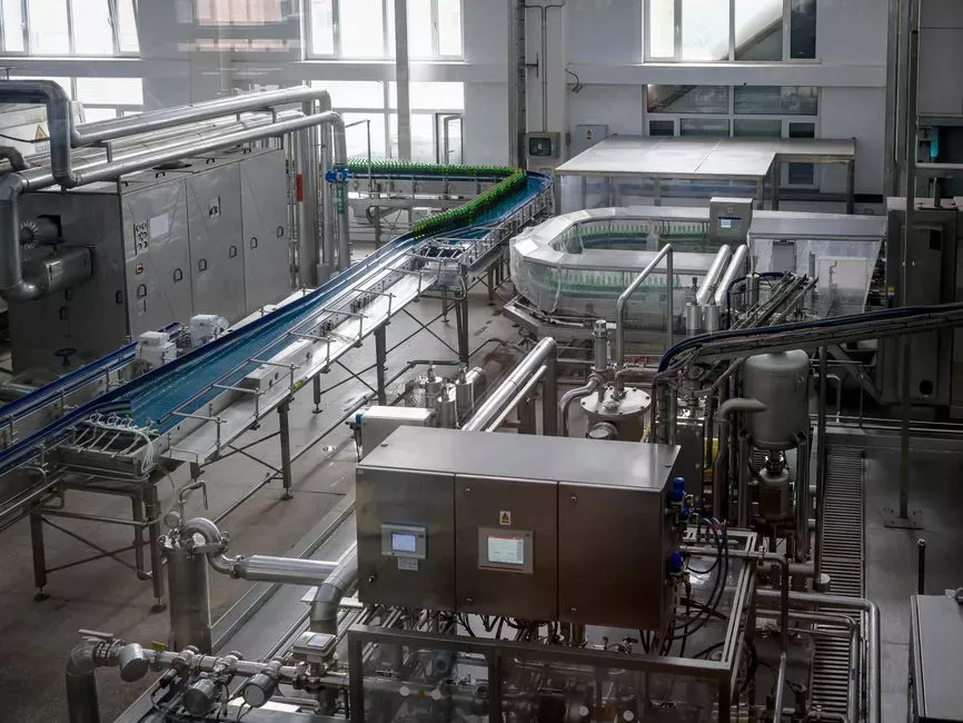
A hospital backup-gen site washing one 2 MW set per week typically operates with a peak shift flow of 3 m³/h and a 4-hour wash window. At 25% recycle the saturator is sized for roughly 0.75 m³/h at 5 bar, and the flotation cell is sized for 0.5 m³ of retention to give about 10 minutes of HRT at peak flow — comfortably inside the 5–20 minute design band. A pre-coagulation mixing stage of 30–60 seconds followed by a 5–10 minute flocculation stage sits upstream of the cell; the floc blanket then meets the depressurised recycle stream in the contact zone.
The skid is typically delivered as a packaged unit with the saturator pump, recycle loop, flotation cell, scum skimmer, and a small sludge pump, plus a PLC and a packaged chemical dosing unit. Site work is limited to the inlet piping, the wash-pad return line, and a power drop. The whole package occupies a footprint of approximately 2 m × 3 m and can sit on a bunded concrete pad outside the generator room. Engineers familiar with the DAF configuration for paper machine seal water will recognise the same design pattern — the difference here is the smaller peak flow and the diesel-specific froth chemistry.
Frequently Asked Questions
What DAF configuration treats diesel generator washdown for reuse or discharge?
A compact pressure-DAF skid with 4–6 bar saturation pressure, 20–80 µm micro-bubbles, and 10–30% recycle, paired with a 50–150 mg/L cationic coagulant (typically PAC) and a 0.5–2 mg/L anionic flocculant, is the standard configuration. For discharge it can stand alone with pH trim; for closed-loop wash-pad reuse, follow it with a coalescing oil-water separator and a 5 µm multimedia polish.
Why not just use an oil-water separator instead of DAF?
A conventional API oil-water separator only removes free oil that rises by gravity. Diesel washdown water cleaned with detergent carries a partially emulsified oil fraction that does not coalesce and rise — it passes straight through an API separator. DAF combines coagulant chemistry to break the emulsion with micro-bubble attachment to float the destabilised droplets, making it the appropriate primary unit whenever detergents are used.
What discharge limit should the DAF hit for diesel washdown?
The widely cited industrial benchmark is 50 mg/L soap-oil-and-grease (SOG) for sewer discharge (MDPI