Home>Blog>Equipment & Technology Guide>Pressure Flotation System Explained: Engineering Mechanics, Efficiency Data & Industrial Selection Guide 2026
Pressure Flotation System Explained: Engineering Mechanics, Efficiency Data & Industrial Selection Guide 2026
Equipment & Technology Guide
Zhongsheng Engineering Team
Pressure Flotation System Explained: Engineering Mechanics, Efficiency Data & Industrial Selection Guide 2025
A pressure flotation system, commonly known as dissolved air flotation (DAF), is an industrial wastewater treatment process that removes suspended solids, oils, greases, and metals by dissolving air under pressure (3-6 bar) and releasing it at atmospheric pressure to form micro-bubbles (10-100 μm). These bubbles adhere to contaminants, causing them to float to the surface for skimming. DAF systems achieve 92-97% TSS removal and 85-95% FOG reduction, making them ideal for industries like food processing, petrochemicals, and mining. Key parameters include hydraulic loading rates (5-15 m/h) and air-to-solids ratios (0.02-0.06).
Why Industrial Plants Struggle with Suspended Solids and FOG Compliance
A food processing plant in the Midwest recently faced a $75,000 fine from the EPA for exceeding its National Pollutant Discharge Elimination System (NPDES) permit limits, specifically for fats, oils, and greases (FOG) which consistently measured above the 100 mg/L threshold set by EPA 2024 guidelines. Such non-compliance scenarios are prevalent across industrial sectors, where inadequate wastewater treatment leads to significant financial penalties and operational inefficiencies. Beyond direct fines, high levels of suspended solids (TSS) and FOG in effluent contribute to increased chemical dosing requirements, frequent downtime for manual sludge removal, and premature fouling of downstream equipment, such as membranes in reverse osmosis (RO) systems, escalating overall operational expenditures (OPEX). For instance, a 10% increase in membrane fouling can lead to a 5-15% rise in energy consumption for pumping, alongside higher chemical cleaning costs. Pressure flotation systems (DAF) effectively address these challenges, reducing FOG by 85-95% and TSS by 92-97%, per EPA 2024 benchmarks, offering a robust solution for maintaining compliance and optimizing plant performance.
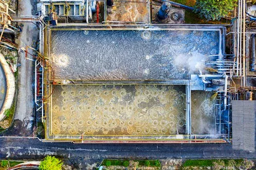
How Pressure Flotation Systems Work: Engineering Mechanics and Process Flow
what is pressure flotation system - How Pressure Flotation Systems Work: Engineering Mechanics and Process Flow
Pressure flotation systems, primarily dissolved air flotation (DAF), operate on fundamental principles of physics and surface chemistry to achieve efficient contaminant separation. The process involves a four-stage mechanism: 1) air dissolution under pressure, 2) pressure release and micro-bubble formation, 3) bubble-particle attachment, and 4) flotation and skimming. Air is dissolved into a recycle stream of treated effluent or a portion of the influent at elevated pressures, typically ranging from 3 to 6 bar, in a saturation tank. According to Henry’s Law, the solubility of air in water increases linearly with the applied partial pressure of the gas; for example, at 3 bar, air solubility is approximately three times its atmospheric solubility, allowing for a super-saturated solution.
Upon release into the flotation tank at atmospheric pressure, the dissolved air rapidly precipitates out of solution, forming a dense cloud of microscopic bubbles ranging from 10 to 100 μm in diameter. These micro-bubbles are crucial for effective separation. Smaller bubbles (10-30 μm) are particularly effective for attaching to fine, colloidal particles and emulsified oils due to their higher surface area-to-volume ratio and lower rise velocity, which allows for more stable attachment. Conversely, larger bubbles (50-100 μm) are better suited for carrying heavier, more flocculated solids or larger oil droplets. Bubble-particle attachment occurs via several mechanisms, including physical entrapment, electrostatic attraction, and hydrophobic interaction, causing the contaminants to rise to the surface. The rate at which the bubble-particle aggregate rises is influenced by Stokes' law, considering the aggregate's density and size relative to the water. Finally, the buoyant "float" layer, comprising concentrated contaminants, is continuously removed from the surface by a skimming device, while the clarified water exits the bottom of the tank. Typical hydraulic loading rates for industrial DAF systems range from 5 to 15 m/h, depending on the wastewater characteristics. A common process flow configuration involves pressurizing a recycle stream (20-50% of the influent flow) with air, mixing it, and then introducing it into the flotation tank through pressure relief valves or nozzles.
Parameter
Description
Typical Range
Effect
Pressure Range
Pressure in saturation tank
3-6 bar (45-90 psi)
Increases air solubility (Henry's Law), affects bubble size distribution. Higher pressure = more dissolved air, smaller bubbles.
Bubble Size
Diameter of air bubbles
10-100 μm
Smaller bubbles (10-30 μm) for fine particles, larger (50-100 μm) for heavier solids. Optimized by pressure and nozzle design.
Recycle Ratio
% of treated effluent recirculated
20-50% of influent flow
Ensures consistent bubble generation and mixing. Higher ratio can improve performance but increases pumping costs.
Air-to-Solids Ratio
Mass of air per mass of suspended solids
0.02-0.06
Critical for effective flotation. Too low, not enough bubbles; too high, wasted energy and turbulence.
Pressure Flotation vs. Alternative Flotation Technologies: Efficiency and Cost Comparison
When selecting a flotation system for industrial wastewater treatment, evaluating different technologies against specific performance and cost metrics is crucial. Pressure flotation (DAF) often stands out, particularly for challenging waste streams, but alternatives like cavitation air flotation (CAF) and induced air flotation (IAF) offer distinct profiles. DAF systems generate micro-bubbles (10-100 μm) by dissolving air under pressure and then releasing it, leading to highly efficient particle attachment and removal. In contrast, CAF systems generate bubbles (typically 50-200 μm) through hydrodynamic cavitation, often using a venturi or rotor-stator mechanism, while IAF systems introduce air directly into the wastewater through mechanical aeration, producing larger, coarser bubbles (100-500 μm).
DAF technology consistently achieves superior removal efficiencies, particularly for fine suspended solids and emulsified oils. DAF systems achieve 95%+ TSS removal and 90%+ FOG removal, making them highly effective for applications such as food processing or petrochemical wastewater. This high performance is attributed to the fine, uniformly distributed bubbles and the controlled attachment mechanism. While DAF typically has a higher capital expenditure (CAPEX) ranging from $500-$1,200/m³/h of treatment capacity, its operational expenditure (OPEX) is often competitive due to lower energy consumption (0.2-0.5 kWh/m³ for pumping and air compression) and reduced chemical requirements in many applications.
CAF systems generally offer moderate removal efficiencies, around 85% for TSS and 80% for FOG, with energy consumption typically between 0.3-0.6 kWh/m³. Their CAPEX is usually lower than DAF, making them an option for less stringent effluent requirements or where capital cost is a primary constraint. For an in-depth exploration of cavitation air flotation, refer to our article on cavitation air flotation system engineering. IAF systems, while having the lowest CAPEX, also exhibit the lowest removal efficiencies, typically 70-80% for TSS and 70% for FOG, and higher energy consumption (0.4-0.8 kWh/m³) due to mechanical aeration. The larger bubble sizes in IAF are less effective for fine particle separation. Therefore, while DAF requires higher initial investment, it delivers superior performance for high-FOG and high-TSS streams, often leading to better long-term compliance and lower overall lifecycle costs for demanding industrial applications.
Technology
Bubble Size (μm)
Energy Use (kWh/m³)
TSS Removal (%)
FOG Removal (%)
CAPEX ($/m³/h)
OPEX ($/m³)
Dissolved Air Flotation (DAF)
10-100
0.2-0.5
92-97
85-95
$500-$1,200
$0.10-$0.30
Cavitation Air Flotation (CAF)
50-200
0.3-0.6
75-88
70-85
$300-$800
$0.15-$0.35
Induced Air Flotation (IAF)
100-500
0.4-0.8
65-80
60-75
$200-$600
$0.20-$0.40
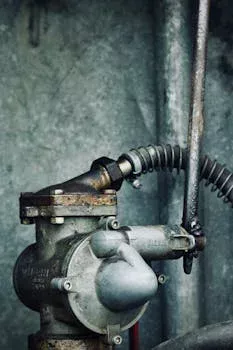
Key Engineering Specifications for Pressure Flotation Systems
what is pressure flotation system - Key Engineering Specifications for Pressure Flotation Systems
The effective design and operation of a pressure flotation system hinge on precise engineering specifications that dictate performance and efficiency. Critical parameters include the pressure range within the saturation tank, which typically operates between 3 and 6 bar. Higher pressures (e.g., 6 bar) significantly increase air solubility, allowing for a greater concentration of micro-bubbles per unit volume, but this also corresponds to higher energy consumption for the compressor. Conversely, lower pressures (e.g., 3 bar) reduce energy costs but may necessitate a larger flotation tank to achieve equivalent removal efficiency due to fewer bubbles.
Bubble size, typically 10-100 μm, is another pivotal factor, influenced by the pressure, air release mechanism (e.g., nozzles, pressure relief valves), and water quality. Hydraulic loading rate, expressed in meters per hour (m/h), defines the volumetric flow rate per unit surface area of the flotation tank. Industry-specific benchmarks for hydraulic loading rates vary significantly: food processing plants often utilize 10-15 m/h for high-FOG streams, while petrochemical applications, dealing with more complex oil emulsions, might operate at lower rates of 5-8 m/h to ensure adequate contact time and separation. The air-to-solids ratio (A/S ratio), ranging from 0.02 to 0.06, represents the mass of dissolved air per mass of suspended solids, directly impacting the number of bubbles available for particle attachment.
Operational constraints also play a significant role. The optimal pH range for DAF systems is typically 6-8, as extreme pH values can destabilize flocs and affect bubble attachment. Wastewater temperature also influences air solubility; temperatures above 40°C can significantly reduce air solubility, requiring higher pressures or larger recycle flows to compensate. The recycle ratio, representing the percentage of treated effluent recirculated and pressurized, commonly falls between 20-50% of the influent flow, balancing performance with pumping costs. Retention time in the flotation tank, usually 15-30 minutes, ensures sufficient time for bubble-particle attachment and float formation.
Parameter
Typical Range
Impact on Performance
Industry-Specific Notes
Pressure Range
3-6 bar
Higher pressure increases air solubility and bubble density, improving removal for fine particles.
Food Processing: often 4-5 bar; Petrochemical: 5-6 bar for complex emulsions.
Bubble Size
10-100 μm
Smaller bubbles (10-30 μm) for colloids; larger (50-100 μm) for heavier flocs.
Optimized by nozzle design and pressure.
Hydraulic Loading Rate
5-15 m/h
Higher rates reduce tank size but may decrease removal efficiency for difficult-to-treat waters.
Insufficient air leads to poor flotation; excessive air wastes energy and can cause turbulence.
Adjust based on influent TSS/FOG load.
Recycle Ratio
20-50%
Influences bubble generation consistency and mixing. Higher ratios improve performance but increase pumping.
Optimize for specific wastewater characteristics.
Retention Time
15-30 min
Ensures adequate time for bubble-particle contact and flotation.
Longer times for more challenging wastewaters.
pH Range
6-8
Optimal range for floc stability and bubble adhesion.
Pre-treatment pH adjustment may be required.
Temperature Range
5-40°C
Higher temperatures reduce air solubility, requiring adjustments to pressure or recycle.
Consider seasonal variations in wastewater temperature.
Industrial Applications: Where Pressure Flotation Systems Excel
Pressure flotation systems are indispensable across a wide array of industrial sectors, providing robust solutions for diverse wastewater challenges and ensuring compliance with stringent discharge regulations. In the Food & Beverage industry, DAF systems are critical for removing high concentrations of FOG and TSS originating from processes like meat packing, dairy production, and vegetable processing. These systems consistently achieve 95% FOG and 92% TSS removal, crucial for meeting EPA NPDES limits for FOG (100 mg/L) and TSS (200 mg/L) that often apply to these facilities. For further insights into industry-specific solutions, explore our food processing wastewater treatment guide.
The Petrochemical sector utilizes DAF for effective separation of oils, greases, and hydrocarbons from process water, preventing environmental contamination and protecting downstream biological treatment units. DAF units in mining operations excel at removing heavy metals and suspended solids from wash water and tailings, with typical removal efficiencies of 90% for metals and 85% for suspended solids (Zhongsheng field data, 2025). This is vital for adhering to strict effluent guidelines, such as those under the EU Industrial Emissions Directive for industrial discharges.
In the Pulp & Paper industry, DAF efficiently removes fibers, fillers, and chemical oxygen demand (COD) components, improving water clarity for reuse and reducing pollutant loads. Municipal wastewater treatment plants deploy DAF for primary clarification, particularly when dealing with high influent TSS and biochemical oxygen demand (BOD) loads, or for sludge thickening. An emerging application is the use of DAF for microplastics removal in textile wastewater, demonstrating up to 90% efficiency in recent 2024 studies, highlighting its versatility for novel contaminant challenges. The adaptability and high efficiency of DAF systems make them a cornerstone technology for industrial wastewater pre-treatment and clarification.
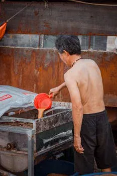
How to Select the Right Pressure Flotation System: A Decision Framework for Industrial Buyers
what is pressure flotation system - How to Select the Right Pressure Flotation System: A Decision Framework for Industrial Buyers
Selecting the optimal pressure flotation system requires a structured evaluation process to ensure it meets both current and future operational demands and compliance targets. The decision framework for industrial buyers involves several critical steps to avoid costly misalignments and maximize return on investment.
Step 1: Define Influent Characteristics and Effluent Targets. Begin by thoroughly characterizing your wastewater influent, including TSS, FOG, COD, BOD, pH, and temperature. Establish clear effluent quality targets (e.g., TSS <50 mg/L, FOG <10 mg/L) based on permit requirements or downstream process needs.
Step 2: Calculate Required Hydraulic Loading Rate and Air-to-Solids Ratio. Based on influent flow rates and contaminant concentrations, calculate the necessary hydraulic loading rate (m/h) and the optimal air-to-solids ratio (typically 0.02-0.06). This determines the required surface area of the DAF unit and the air demand. Detailed engineering calculations for DAF systems can be found in our comprehensive guide here.
Step 3: Compare System Types and Configurations. Evaluate different DAF system designs, such as rectangular vs. circular tanks, and full-flow vs. recycle pressurization. Rectangular DAF units are often preferred for larger flows and ease of modular expansion, while circular units can offer better hydraulic stability. Recycle pressurization is most common, but full-flow can be suitable for low-TSS waters. Consider the ZSQ series DAF system for industrial wastewater, which offers various configurations.
Step 4: Evaluate Vendor Specifications and Features. Scrutinize vendor proposals for critical engineering details. Look for robust construction materials like 316 stainless steel for corrosion resistance, PLC-controlled skimmers for automated sludge removal, and integrated chemical dosing systems for optimal flocculation. An automatic chemical dosing system can significantly improve DAF performance by ensuring precise coagulant and flocculant addition.
Step 5: Perform Comprehensive CAPEX/OPEX Analysis. Conduct a detailed financial assessment, considering both capital expenditure (CAPEX) for equipment purchase and installation, and operational expenditure (OPEX) including energy consumption, chemical costs, sludge disposal, and maintenance. DAF systems typically cost $500-$1,200/m³/h (CAPEX) with OPEX of $0.10-$0.30/m³ (energy, chemicals, maintenance). A comprehensive analysis helps predict the total cost of ownership and calculate the return on investment (ROI) through reduced fines, lower downstream treatment costs, and potential water reuse.
For complex wastewater streams, a decision tree can guide system selection: if FOG >500 mg/L, a DAF system is highly recommended. If TSS >1,000 mg/L, a DAF system may be combined with a primary clarifier or a lamella clarifier for enhanced solids removal. Pilot testing is also highly recommended for highly variable or novel waste streams to validate design parameters and performance.
Decision Criteria
Consideration
Impact on Selection
Influent FOG Concentration
Low (<50 mg/L) to Very High (>1000 mg/L)
Higher FOG requires DAF with optimized chemical pre-treatment.
Influent TSS Concentration
Low (<100 mg/L) to Very High (>2000 mg/L)
High TSS may necessitate DAF + primary clarification or larger DAF units.
Effluent Quality Targets
Discharge limits (NPDES, local) or reuse standards
Dictates removal efficiency required and whether DAF alone is sufficient.
Footprint Availability
Space constraints for equipment installation
Influences choice between rectangular (expandable) and circular (compact) DAF designs.
Favors DAF for long-term efficiency despite higher CAPEX.
Capital Budget (CAPEX)
Initial purchase and installation cost
May lead to considering CAF/IAF for lower initial investment, but at performance trade-off.
Wastewater Variability
Fluctuations in flow, concentration, pH, temperature
Requires robust DAF design with automated controls (e.g., pH, chemical dosing).
Frequently Asked Questions
What is the primary difference between DAF and sedimentation?
DAF uses the principle of flotation, where air bubbles attach to contaminants, making them buoyant and causing them to rise to the surface for skimming. Sedimentation relies on gravity, allowing heavier particles to settle to the bottom. DAF is particularly effective for particles with densities similar to water, such as oils, greases, and fine suspended solids, which do not settle well by gravity alone.
How does temperature affect DAF system performance?
Temperature significantly impacts air solubility in water; as temperature increases, air solubility decreases. This means that at higher wastewater temperatures (e.g., >40°C), more air pressure or a larger recycle flow might be needed to achieve the same amount of dissolved air and micro-bubble generation, potentially increasing energy consumption.
What chemicals are typically used in conjunction with a DAF system?
Common chemicals used with DAF systems include coagulants (e.g., aluminum sulfate, ferric chloride) to destabilize particles and promote aggregation, and flocculants (e.g., anionic or cationic polymers) to bind smaller flocs into larger, more buoyant aggregates that attach more readily to air bubbles. pH adjusters may also be used to optimize chemical reactions.
What is the typical sludge concentration from a DAF unit?
The sludge (float) removed from a DAF unit typically has a solids concentration ranging from 2% to 6%, depending on the influent characteristics and chemical conditioning. This concentration is generally higher than that achieved by primary sedimentation, reducing downstream sludge dewatering requirements.
Can DAF systems handle fluctuating influent loads?
Yes, DAF systems can be designed to handle fluctuating influent loads, but it requires careful engineering. Features like variable speed drives for pumps, automated chemical dosing systems, and adjustable skimmer speeds help maintain performance during variations in flow rate or contaminant concentration. Pilot testing is often recommended for highly variable waste streams.
Our team of wastewater treatment engineers has over 15 years of experience designing and manufacturing DAF systems, MBR bioreactors, and packaged treatment plants for clients in 30+ countries worldwide.