Why Stamping Press Oily Water Needs ZLD: 2026 Compliance & Water Reuse Drivers
EPA 40 CFR Part 467 caps oil and grease discharge at <10 mg/L and COD at <125 mg/L for metalworking facilities, thresholds that conventional clarifiers cannot consistently meet for stamping press effluent. A stamping line running 50 m³/h with 500–5,000 mg/L oil/grease and 1,000–10,000 mg/L COD will fail a discharge permit on a single shift where coolant carryover spikes, and surcharges under EPA's penalty matrix can exceed ¥500,000 per violation (per EPA 40 CFR Part 467). In parallel, the 2026 EU Industrial Emissions Directive (IED) update requires 95%+ water recovery for metalworking plants, with non-compliance fines capped at 4% of annual revenue.
Beyond compliance, freshwater cost in China's coastal industrial parks now runs ¥5–10/m³, and a 50 m³/h stamping line consuming municipal water at that rate spends ¥2.2–4.4M/year before treatment. A Shanghai auto-parts plant that retrofitted ZLD in 2025 reported ¥2.4M/year in combined freshwater savings and avoided surcharges, with the 30% ZLD capital grant from the local environmental bureau cutting payback to under 3 years. ESG frameworks have caught up: GRI 303 now requires audited recovery rates and sludge disposal pathways for any facility reporting water withdrawals above 50,000 m³/year, and most Tier-1 OEM suppliers will not renew contracts with plants lacking ZLD certification by Q4 2026.
ZLD is no longer an option for greenfield stamping capacity; it is the permitting baseline.
Step 1: Characterize Stamping Press Oily Water Feed—Key Parameters & Sampling Protocol
Undersized ZLD systems almost always trace back to feed characterization that missed a hydraulic or load peak. Stamping press effluent is not a constant stream; it surges when presses purge coolant, when shift-change washdowns hit the sump, and when die-change operations dump emulsified lubricant. A robust sampling campaign captures both baseline chemistry and transient extremes before any equipment is specified.
Key parameters to measure across a 7-day campaign: oil and grease (500–5,000 mg/L typical), TSS (200–1,500 mg/L), COD (1,000–10,000 mg/L), pH (6–9), temperature (30–60°C), and emulsifier concentration reported as total non-ionic surfactant (typically 50–300 mg/L in plants using semi-synthetic coolants). Synthetic and semi-synthetic coolants form stable oil-in-water emulsions that resist gravity separation; DAF alone will underperform unless coagulant dose is raised to 15–20 mg/L PAC versus 5–10 mg/L for straight mineral oils.
| Parameter | Typical Range | Sampling Point | Method |
|---|---|---|---|
| Oil & Grease | 500–5,000 mg/L | Press sump, central pit | EPA 1664 (HEM) |
| TSS | 200–1,500 mg/L | Central pit, EQ tank | EPA 160.2 |
| COD | 1,000–10,000 mg/L | EQ tank outlet | EPA 410.4 |
| pH | 6–9 | Press sump, EQ tank | Online probe + grab |
| Temperature | 30–60°C | EQ tank inlet | PT100 with logger |
| Emulsifier (TNIS) | 50–300 mg/L | Press sump | Wickbold titration |
Pull 24-hour composite samples at three locations: the press sump (worst-case emulsified load), the central collection pit (mixed shop flow), and the equalization tank outlet (post-surge attenuation). Use auto-samplers on the pit and tank; manual grabs every 2 hours from the sump during press cycles. Record instantaneous flow at each point so load (kg/h) can be back-calculated, not just concentration. A sample log sheet should flag shift changes, die changes, and coolant top-ups, the three events that drive 80% of hydraulic and chemical peaks in stamping operations. DAF systems for stamping press oily water pretreatment are sized off these peaks, not the daily average.
Step 2: Define Recovery Goals—Balancing Compliance, CAPEX, and OPEX for 2026
Recovery target selection is the single decision that most influences both the capital cost and the operating economics of a ZLD system. Three tiers cover the realistic operating range for stamping plants: 90% recovery meets minimum regulatory compliance and is the lowest-cost path for facilities with limited capital; 95% recovery is the cost-optimum point where membrane and evaporation CAPEX is balanced against freshwater and discharge savings; 98%+ recovery is the ESG-driven ceiling, typically justified only by water-scarce sites, corporate sustainability mandates, or eligibility for government ZLD grants.
The trade-off is sharper than most engineers expect. Pushing from 90% to 95% recovery on a 50 m³/h system adds roughly ¥4M in CAPEX (driven by a second RO stage and a smaller brine concentrator) but reduces OPEX from ¥150/m³ to ¥120/m³ because less freshwater is purchased and less concentrate is hauled offsite. Pushing to 98% adds another ¥6M for a mechanical vapor recompression (MVR) crystallizer, with marginal OPEX improvement because the evaporator consumes 10–15 kWh/m³ against the RO's 3–5 kWh/m³.
| Recovery Target | Typical CAPEX (50 m³/h) | OPEX (¥/m³ treated) | Driver |
|---|---|---|---|
| 90% | ¥8M | ¥150–180 | Minimum compliance |
| 95% | ¥12M | ¥120–140 | Cost-optimum / EU IED 2026 |
| 98%+ | ¥18M+ | ¥160–200 | ESG / ZLD grant eligibility |
For 2026 projects targeting EU OEM supply chains, 95% is effectively the floor. Plants in China's western provinces where freshwater tariffs are subsidized below ¥3/m³ may find 90% economically defensible, but the same plants face increasing pressure from provincial environmental bureaus to align with national ZLD targets by 2028.
Step 3: Allocate Recovery by Process Stage—Pretreatment, Membranes, and Evaporation
Recovery allocation across stages determines whether a ZLD train runs cleanly or fouls within months. The conventional split for stamping press effluent is 60–70% of total recovery in pretreatment (DAF + pH adjustment), 20–30% in the membrane stage (RO or NF), and 5–10% in evaporation/crystallization. Skewing recovery toward the membrane stage to "save" on evaporation CAPEX is the most common error, and it produces rapid membrane fouling that wipes out any upfront savings within the first year.
Pretreatment must drive oil/grease below 50 mg/L and TSS below 100 mg/L before water contacts RO membranes. Well-designed DAF units achieve 92–97% oil removal on stamping effluent, but only with the right coagulant and flocculant chemistry, typically 5–15 mg/L PAC plus 1–3 mg/L anionic polyacrylamide, and a hydraulic retention time of 20–30 minutes. Biological treatment using MBR systems for biological treatment of oily wastewater can polish COD from 1,000–10,000 mg/L down to 200–500 mg/L before membranes, which extends RO element life from 12 to 24+ months on oily feeds.
The membrane stage should use oil-resistant PVDF or polyamide-thin-film elements operated at 15–25 LMH flux; pushing above 25 LMH on oily RO feeds accelerates fouling exponentially. Two-pass RO is standard for 95% recovery, with inter-stage booster pumps and CIP provisions sized for weekly cleanings. Permeate COD should be <50 mg/L for direct reuse in press coolant make-up or rinsing.
| Stage | Recovery Share | Target Output | Key Equipment |
|---|---|---|---|
| Pretreatment (DAF, pH adjust) | 60–70% | Oil <50 mg/L, TSS <100 mg/L | DAF, coagulation tank |
| Biological (MBR / anaerobic filter) | 5–15% | COD <500 mg/L | MBR or AF bed |
| Membrane (RO / NF) | 20–30% | Permeate COD <50 mg/L | 2-pass RO, PVDF |
| Evaporation / Crystallization | 5–10% | Zero liquid discharge | Brine concentrator or MVR |
Evaporation handles the RO concentrate, which typically runs TDS >30,000 mg/L with residual COD of 200–800 mg/L. A brine concentrator (multi-effect evaporator) costs less upfront but consumes more steam; MVR costs more but uses 60–70% less thermal energy. The decision is usually driven by whether the plant has waste heat or low-pressure steam available, MVR pays back in under 2 years at sites with electricity below ¥0.6/kWh, while multi-effect is preferable where steam is already on-site. RO systems for ZLD recovery of stamping press water should be specified with concentrate recycle back to the evaporator feed tank to maintain mass balance.
One operational point most sizing guides skip: biological stages in ZLD trains, particularly anaerobic filter beds, require a 2–6 week stabilization period before reaching steady-state COD removal. Plan for this in commissioning; do not judge biological performance on the first month of data (per S2, S3).
Step 4: Size Buffering and Utilities—Equalization, Chemical Dosing, and Energy Demand
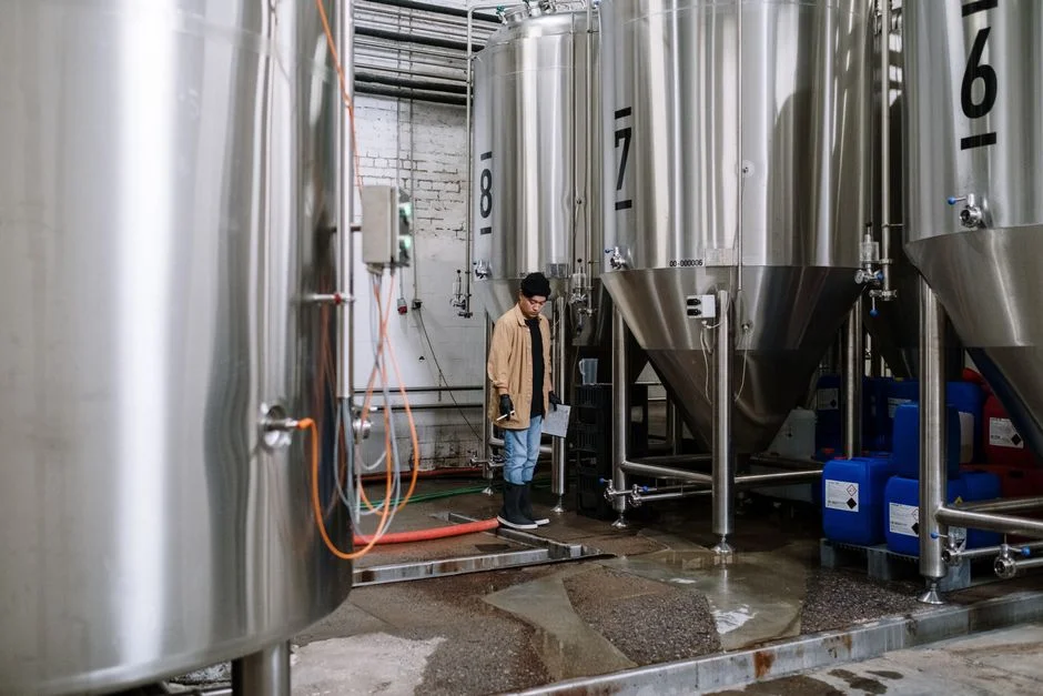
Equalization tank sizing is the most undervalued number in a ZLD design. Stamping press effluent can spike to 2–3× average flow during shift changes and die-change washdowns, and a tank sized only for daily average will pass those surges straight through to the DAF, where they short-circuit the flotation zone and carry oil overboard. The working rule: size equalization at 1.5–2× average daily flow, which means a 75–100 m³ tank for a 50 m³/h average line. Include a mechanical mixer (not just an air sparger) to prevent oil creaming at the surface, and a corrugated plate interceptor upstream if oil pad thickness exceeds 50 mm.
Chemical dosing systems must be specified for the worst-case feed condition, not the design average. Chemical dosing for ZLD pretreatment typically includes NaOH or H₂SO₄ for pH adjustment to 7–8 before DAF, 5–15 mg/L PAC as coagulant, 1–3 mg/L anionic PAM as flocculant, and phosphonate-based antiscalant at 2–5 mg/L injected ahead of the RO high-pressure pump. Dosing pumps should have 4–20 mA proportional control tied to inline pH and flow meters; a one-size setpoint fails when emulsifier concentration doubles during a coolant top-up event.
Energy demand breaks down as 3–5 kWh/m³ for the DAF + RO train and 10–15 kWh/m³ for the evaporator. A 50 m³/h ZLD plant running 6,000 hours/year at 8 kWh/m³ blended average consumes roughly 2.4 GWh/year, about ¥1.5M/year at industrial tariffs. On-site solar can offset 15–25% of this at sites with available roof or land area, but it does not change the peak demand charge, which is usually the larger line item for metalworking plants running two-shift operations.
Step 5: Validate Operability—Upset Conditions, Redundancy, and Future Growth
A ZLD system that performs perfectly on the design day will fail within a year if it cannot ride out the upset conditions that occur monthly in any stamping plant. Validation means deliberately simulating the worst credible feed condition: an oil spike to 10,000 mg/L from a coolant dump, a pH swing to 4 or 10 from a cleaning chemical cross-connection, a temperature excursion to 70°C from a press hydraulic failure, and a flow surge to 2× average during a coordinated plant washdown. Each of these should be tested during commissioning, not assumed away.
Redundancy is non-negotiable for any ZLD system feeding a production-critical line. The minimum baseline: dual DAF skimmers with independent drives, 100% spare RO elements on site, redundant high-pressure pumps with auto-changeover, and a backup chemical dosing pump for each reagent. A single DAF pump failure can shut down the entire train within 4 hours as oil carries through to the membranes.
Future growth is where most plants leave money on the table. Civil works, tank foundations, and pipe headers should be sized for 2× the phase-1 capacity even when only 50% of that capacity is being installed. The incremental cost of oversizing a concrete foundation or running a larger-diameter header is typically 3–5% of the project; the cost of retrofitting capacity in a live plant is 30–50%. ZLD sizing for other industrial oily water streams follows the same phase-growth principle when comparing paint booth curtain water with stamping effluent. For a 50 m³/h phase-1 design, build for 100 m³/h and avoid the 2028 retrofit premium.
Cost-Optimized ZLD Design for Stamping Press Oily Water: CAPEX, OPEX, and ROI
The cost-optimal ZLD design for a 50 m³/h stamping press line in 2026 hits 95% recovery, two-pass RO with MVR evaporation, and a phased civil works envelope. CAPEX ranges ¥8–18M depending on recovery target, with the dominant cost drivers being the RO membrane area (about 25% of total), the evaporator (20–30%, with MVR at the upper end), and DAF + MBR pretreatment (15–20%). Stainless steel 316L versus carbon steel lining in the evaporator alone can swing CAPEX by ¥1.5–2M, but the upgrade pays back within 4 years on sites with chloride-bearing coolant carryover.
OPEX runs ¥120–200/m³ treated across the realistic operating range, broken down roughly as 35–40% energy, 20–25% chemicals and consumables, 15–20% labor and maintenance, and 15–25% sludge disposal. Sludge hauling is the line item most engineers underestimate: oily DAF skimmings classified as hazardous waste in most Chinese provinces cost ¥2,500–4,000/ton to transport and incinerate. Reducing oily sludge yield by even 20% through better DAF chemistry directly improves OPEX by ¥8–15/m³.
| Cost Category | 90% Recovery | 95% Recovery | 98% Recovery |
|---|---|---|---|
| CAPEX (¥M, 50 m³/h) | 8 | 12 | 18+ |
| OPEX (¥/m³) | 150–180 | 120–140 | 160–200 |
| Payback vs. freshwater + surcharges | 4–5 yr | 3–4 yr | 5–7 yr |
| Best fit | Compliance-only sites | Most 2026 projects | ESG / grant-driven |
Three ROI accelerators can cut payback by 30–50%. First, China's 30% ZLD capital grant (still active in Jiangsu, Guangdong, and Shanghai as of 2026) directly reduces upfront CAPEX. Second, water reuse incentives of ¥2/m³ for plants achieving >95% recovery are paid through provincial water resource bureaus. Third, ESG tax credits offer a 15% reduction in corporate income tax for facilities adopting certified ZLD under the China Green Finance catalog. Plants stacking all three typically see payback drop to 18–24 months. Regional ZLD incentives and compliance requirements vary significantly, so verify eligibility with local environmental authorities before finalizing the budget model.
Common ZLD Sizing Mistakes for Stamping Press Oily Water (and How to Avoid Them)
Undersized equalization tanks. A tank sized to daily average flow, rather than 1.5–2× that volume, passes hydraulic surges straight to the DAF and RO, where they cause oil carryover and flux instability. The fix is mechanical: size the EQ tank for peak shift flow with a minimum 4-hour retention at average flow.
Ignoring emulsifier impact. Semi-synthetic and synthetic coolants create stable oil-in-water emulsions that DAF alone cannot break. Plants running these coolants need 15–20 mg/L PAC versus 5–10 mg/L for mineral oil systems, plus a flocculant stage. Skipping this turns the DAF into a pass-through and sends emulsified oil straight to the RO, where it fouls within weeks.
Overlooking temperature spikes. Stamping press coolant can reach 60–70°C during press failure events. RO membranes are rated to 45°C maximum; above that, both flux and rejection drop sharply, and element life halves. Install a plate heat exchanger ahead of the RO when feed temperature regularly exceeds 40°C.
Skipping redundancy. Single-point failures on DAF skimmers, RO high-pressure pumps, or chemical dosing shut the entire ZLD train down. Redundancy is not optional for production-critical lines: dual skimmers, N+1 pump configuration, and spare membrane elements on site. The cost of full redundancy on a 50 m³/h system is typically ¥800K–1.2M, less than one week of unplanned downtime at most stamping plants.
For sites also handling metal-bearing rinsewater, pretreatment for heavy metals in metalworking wastewater should be integrated upstream of the DAF to prevent metal-bearing sludge from contaminating the oil phase.
Frequently Asked Questions
What is the minimum oil and grease level a DAF can achieve on stamping press effluent?
A properly sized DAF with the correct coagulant chemistry (5–15 mg/L PAC plus 1–3 mg/L anionic PAM) achieves 92–97% oil removal, bringing 500–5,000 mg/L influent down to 15–50 mg/L. Plants using semi-synthetic coolants should expect the higher end of residual oil and plan coagulant dose at 15–20 mg/L PAC.
How long does a ZLD system take to reach stable recovery after startup?
Biological stages (MBR or anaerobic filter) require 2–6 weeks to reach steady-state COD removal. Membrane stages typically reach design flux within 24–48 hours, but operators should wait at least 30 days before judging overall recovery against design targets, since upstream biology directly affects downstream membrane loading during this period.
Can a ZLD system for stamping press water reuse the treated effluent as coolant make-up?
Yes, and this is the standard configuration for 95%+ recovery plants. RO permeate typically runs COD <50 mg/L, TDS <50 mg/L, and is hardness-free, which actually extends coolant life compared to municipal freshwater. The 5–10% evaporation/crystallization step disposes of the RO concentrate as solid salt rather than liquid waste, which simplifies permitting and removes the discharge pathway entirely.
What is the 2026 regulatory threshold that forces metalworking plants to install ZLD?
In China, EPA 40 CFR Part 467 equivalent discharge limits (10 mg/L oil/grease, 125 mg/L COD) combined with provincial ultra-low emission targets make ZLD the only compliant path for most stamping plants discharging to surface water. In the EU, the 2026 Industrial Emissions Directive update requires 95%+ recovery for metalwashing operations, with fines up to 4% of revenue for non-compliance. Plants exporting to EU OEM supply chains are effectively required to meet the EU standard regardless of location.