Why deinking reject water breaks an unprotected DAF
Deinking reject water breaks a dissolved air flotation unit because it arrives as a heterogeneous slurry, not a colloidal suspension, and the DAF is engineered for the latter. A single shift on a typical 1,200 t/d deinking line delivers a reject stream carrying long fibers in the 3–8 mm range, fines and fillers (kaolin, GCC, TiO2) below 200 μm, stickies under 0.5 mm (hot-melts, PSA contaminants, waxes), residual ink particles in the 10–200 μm band, and a load of fatty-acid/surfactant collector carryover from the upstream ink-flotation cell. Total suspended solids swing from roughly 2,000 to 15,000 mg/L over a shift as furnish and reject screw speed change (HydropureWater field data, 2026).
Three failure modes follow from that composition. First, the fibrous fraction consumes air bubbles at the contact zone, so the air-to-solids ratio collapses and float yield drops. Second, residual fatty-acid collectors depress bubble–particle attachment efficiency because they compete for the air–water interface. Third, oversized fibers and baling wire rag the recycle pump impeller and jam the surface skimmer, taking the unit offline. Direct DAF on this stream is the wrong first unit operation; the engineering principle is that DAF performs suspended-solids polishing, not raw-stream clarification. Upstream conditioning is the work that makes the DAF feed a stable colloidal suspension. The first tool is a rotary mechanical bar screen sized for the debris load, not for hydraulic throughput alone.
Stage 1 — Coarse screening and trash removal
Specify 6–10 mm aperture bar or perforated screens as the floor for any deinking reject feed to a DAF; finer 3–5 mm perforations are only justified on recycled-fiber lines with documented high plastic contamination. A static bar screen blinds within hours on this stream because the long-fiber fraction mats across the openings; rotary drum or rotary bar geometry is the correct duty class because the moving element sheds the mat continuously. The rotary mechanical bar screen in the GX class is built for exactly this service.
Define the capture target as >95% of particles larger than 6 mm, which is the threshold above which items — baling wire, PPE fragments, wood splinters, and plastic straps — will reach the DAF recycle pump and either rag the impeller or score the white-water side of the saturator. The operating envelope is headloss below 300 mm at peak instantaneous flow, with automatic brush discharge into a compactor or covered dumpster so debris does not re-enter the floor drain. A daily inspection of the discharge chute is cheap insurance; the cost of one impeller rebuild exceeds a year of screen maintenance.
Stage 2 — Fiber and filler recovery (sidestream thickener)
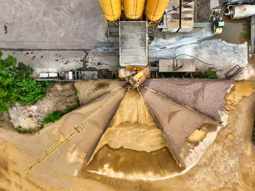
Fiber recovery is the single highest-impact step in the train because it returns usable furnish to stock prep and cuts the load the DAF must handle. Use a sidehill screen, drum thickener, or gravity decker as the primary recovery device. Well-tuned units return 50–70% of long fibers and fillers to the machine chest, which both reduces freshwater demand in the furnish loop and materially shrinks the wastewater flow reaching the DAF (per TAPPI deinking process references, 2025-09).
The DAF-feed TSS target after this stage is 1,500–3,000 mg/L. This band is deliberate: high enough that the stream still has the solids concentration needed for stable floc formation, and low enough that the saturator's air demand stays inside the 0.01–0.1 g air/g solids ratio that a standard micro-bubble DAF can deliver at 10–30% recycle. Floatables — stickies, waxes, hot-melt contaminants — concentrate in the thickener overflow because they preferentially ride the water film. That is good, because it puts the worst contaminants in a small, concentrated stream where chemistry works efficiently rather than diluting them across the entire DAF feed.
Watch the recovered fiber: over-thickening drops brightness and creates a second reject stream that defeats the purpose of the sidestream. Freeness (CSF) and ISO brightness of the recovered stock should be logged on the same shift schedule as the wastewater parameters.
Stage 3 — Equalization, pH, and temperature conditioning
The equalization basin is what turns a variable reject stream into a stable feed. Size the basin for 4–8 hours of hydraulic residence; this window is enough to damp the 2,000–15,000 mg/L TSS swing noted in Stage 1 down to a feed that drifts by no more than ±20% on an hourly basis. Aerated mechanical mixing keeps solids in suspension without shearing flocs that will form in the next stage; a low-speed propeller at the floor of the basin at G ≈ 50–80 s⁻¹ is typical.
Hold pH at 6.5–7.5. Below 6, fatty-acid collectors protonate and drop out of solution as free acid, precipitating before they can do useful work; above 8, they ionize too strongly, lose affinity for ink particles, and re-disperse what was already floated. Field data shows DAF removal efficiency drops 30–50% when pH drifts outside this band (HydropureWater field data, 2026).
Hold temperature at 35–45 °C. Cold stock below 25 °C raises water viscosity, slows bubble rise velocity, and leaves a turbid effluent. Hot stock above 55 °C flashes micro-bubbles prematurely in the saturator and collapses the contact zone — the float goes thin and cloudy at the same time. Use the basin temperature transmitter to feed the steam or hot-water control valve; do not rely on manual setpoints. The chemistry step downstream is sensitive to both pH and temperature, which is why the automatic chemical dosing system on Stage 4 should be cross-linked to both signals.
Stage 4 — Coagulant and flocculant dosing
The working recipe for deinking reject is a dual-polymer scheme. Dose a cationic coagulant — polyaluminum chloride (PAC) is preferred over ferric chloride because of its wider working pH band and lower sludge volume — at 50–200 mg/L, then dose a high-molecular-weight anionic flocculant at 1–5 mg/L. The mechanism is sequential: PAC neutralizes the negative surface charge on colloidal ink and stickie particles, and the anionic flocculant bridges the destabilized particles into 0.5–2 mm flocs that DAF micro-bubbles can lift reliably.
The dosing sequence is not optional. Inject the coagulant first into a flash-mix zone with 30–60 s residence at G ≈ 300–500 s⁻¹, then add the flocculant into a slow-mix zone with 5–10 min residence at G ≈ 20–50 s⁻¹, and only then let the stream reach the DAF contact zone. Reversing the order coats the flocculant onto stable colloids and wastes both reagents. The automatic chemical dosing system should meter both pumps from a single PLC with separate calibration curves.
Failure modes are concrete. Under-dosing of either reagent leaves a turbid effluent with a streaming current value far from zero. Over-dosing of the anionic flocculant above ~5 mg/L restabilizes the colloids and creates a viscous, persistent foam blanket on the DAF surface that the skimmer cannot remove cleanly. Drive the dosing from on-line diagnostics: streaming current for charge demand, zeta potential with a target of −5 to +5 mV, and a visual floc-size check at the inlet weir (target 0.5–2 mm). Jar testing on every furnish change is mandatory; lab bench numbers do not transfer one-to-one to the full-scale saturator.
Pre-DAF parameter summary
The table below consolidates the numeric bands an engineer needs to drop into a PFD. Boundary conditions for the DAF itself — 10–100 μm bubble diameter, 4–6 bar saturator pressure, 10–30% recycle ratio, and 0.01–0.1 g air/g solids — drive the upstream targets, not the other way around. Site jar testing is mandatory to fine-tune polymer dose and pH, but the bands below are the starting point.
| Stage | Unit operation | Design parameter | Target band | Instrument / control loop |
|---|---|---|---|---|
| 1. Coarse screening | Rotary bar / drum screen | Aperture | 6–10 mm (3–5 mm on high-plastic lines) | Headloss transmitter, <300 mm |
| 2. Fiber recovery | Sidehill / drum thickener | DAF-feed TSS | 1,500–3,000 mg/L | Online TSS probe downstream |
| 3. EQ + conditioning | Aerated EQ basin | HRT | 4–8 h | Level + flow totalizer |
| 3. EQ + conditioning | pH correction | pH | 6.5–7.5 | pH probe → CO2/NaOH dosing |
| 3. EQ + conditioning | Temperature control | Temperature | 35–45 °C | RTD → steam valve |
| 4. Coagulant | PAC dosing | Dose | 50–200 mg/L | Streaming current controller |
| 4. Flocculant | Anionic polyacrylamide | Dose | 1–5 mg/L | Stroke-rate pump + jar test |
| 4. Floc condition | Slow-mix | G, residence | 20–50 s⁻¹, 5–10 min | VFD on mixer |
| DAF boundary | Micro-bubble DAF | Bubble size | 10–100 μm | Saturator pressure 4–6 bar |
| DAF boundary | Micro-bubble DAF | Recycle ratio | 10–30% | Recycle flowmeter |
| DAF boundary | Micro-bubble DAF | Air-to-solids | 0.01–0.1 g air/g solids | Derived: recycle × air saturation ÷ TSS load |
Linking the pretreated stream to the DAF unit
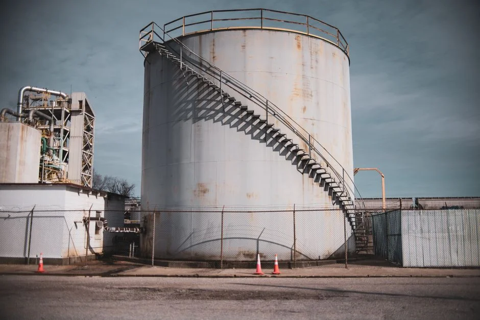
With the four-stage train in front of it, the DAF has one job: polish residual TSS from roughly 2,000 mg/L down to below 100 mg/L, drop turbidity below 30 NTU, and remove >90% of suspended stickies and inks. The dissolved air flotation system is sized for this duty across 4–300 m³/h in 13 standard models, with automatic skimming and a saturator matched to the recycle ratio set in Stage 4.
Two downstream details complete the loop. First, the DAF float (skimmings) typically runs 3–5% solids; route this sludge to a plate and frame filter press to reach a 30–35% dry cake suitable for co-incineration or landfill, rather than paying to haul water. Second, the clarified DAF effluent can usually be recycled to the pulp machine seal-water loop or polished further; engineers sizing an MBR downstream should see the MBR configuration for deinking reject water guide for the next unit operation.
Troubleshooting matrix — DAF upsets and their upstream causes
The four most common DAF upsets on deinking reject are listed below with the upstream root cause. A daily walk-around checklist — pH meter calibration, polymer pump stroke verification, EQ basin temperature log, and DAF skimmer torque reading — catches most of these before they become off-spec events.
| DAF upset observed | Most likely upstream cause | First corrective action |
|---|---|---|
| Cloudy DAF effluent, high turbidity | pH drift outside 6.5–7.5, or under-dose of PAC (streaming current well off zero) | Calibrate pH probe, jar-test a +25% PAC dose |
| Thin, sluggish float layer | Over-dose of anionic flocculant (>5 mg/L) restabilizing colloids, or temperature below 25 °C | Reduce flocculant pump stroke, check steam valve on EQ basin |
| Scraper jamming or recycle pump ragging | Inadequate coarse screening — fibers, wire, or plastic >6 mm passing through | Inspect screen aperture, check for blinded panels |
| Bubble collapse in the contact zone, weak float | Temperature above 55 °C flashing bubbles, or saturator pressure below 4 bar | Check RTD on EQ basin, verify saturator pressure transmitter and compressor |
Frequently asked questions
What screen size should be used before DAF on deinking rejects?
6–10 mm bar or perforated aperture. Finer 3–5 mm perforations are only justified on recycled-fiber lines with documented high plastic contamination, because the finer the screen the faster it blinds and the higher the headloss penalty.
What pH is required for DAF on deinking reject water?
6.5–7.5. This band keeps the residual fatty-acid collectors from the ink-flotation cell in their active, partially ionized form — protonated below 6, over-ionized above 8 — and field data shows DAF removal drops 30–50% outside this window.
Can DAF handle raw deinking reject without fiber recovery?
Not recommended. With TSS above roughly 3,000 mg/L and long fibers in the 3–8 mm range, the air-to-solids ratio collapses at standard 10–30% recycle and bubble–particle contact fails. Sidestream fiber recovery brings the DAF feed into the 1,500–3,000 mg/L band where micro-bubble DAF performs as designed.
Which coagulant works best — ferric chloride, PAC, or alum?
PAC is preferred for deinking reject because it has a wider working pH band, lower effective dose on a mg/L basis, and generates less iron-stained sludge. Ferric chloride is acceptable but stains equipment and pipes; alum is generally too pH-sensitive for the 6.5–7.5 band.
What DAF effluent turbidity protects a downstream MBR?
Sustained turbidity below 30 NTU. Above that, MBR membrane fouling rate climbs sharply and chemical cleaning intervals shorten; the DAF polishing target in this article is set specifically to keep the downstream MBR in its design operating envelope.