Why Bleach E-Stage Effluent Is a Distinct DAF Challenge
Alkaline E-stage filtrate from an ECF bleach plant typically carries pH 10-12, temperature 60-80°C, TSS 200-1,500 mg/L, COD 1,000-3,000 mg/L, and residual H2O2 of 50-500 mg/L, and it cannot be treated with the same dissolved air flotation unit used for debarking runoff or general pulp wastewater (hydrogen peroxide, peracetic acid, and sodium hypochlorite are the common bleach agents per the PMC review of industrial wastewater treatment). The combination of high pH, residual oxidant, and 60-80°C service temperature is what separates this stream from every other P&P DAF application, and the DAF configuration for debarking runoff reflects a much lower temperature and near-neutral pH envelope.
Standard carbon-steel DAF tanks fail in E-stage service for two compounding reasons. Residual H2O2 and free chlorine attack mild steel at rates exceeding 0.5 mm/year once pH climbs above 10, and the 60-80°C feed water drops air solubility by roughly 40% versus 25°C, shrinking the working bubble population and collapsing the float blanket. A mill that bolts a general-purpose DAF onto E-stage filtrate is buying an 18-24 month tank and a remediation event, not a treatment unit.
Positioning DAF as an upstream process change — rather than a polishing step at the end of pipe — is consistent with the BioResources 2024 P&P review, which identifies DAF, filtration save-alls, and kidney loops as the three unit operations that cut both pollutant load and effluent volume at the source. For E-stage specifically, the DAF is a load-reduction tool that protects the downstream biotreatment stage from pH swings and residual oxidant breakthrough.
DAF Sizing Parameters That Actually Matter for E-Stage
Micro-bubble diameter of 10-50 µm at 4-6 bar saturation pressure is the working window for E-stage colloids, most of which fall in the 5-100 µm size band. The Chemosphere 2024 flotation-mechanics work confirms that collision efficiency between a rising bubble and a suspended particle is governed by bubble size distribution, bubble velocity, and the surface charge of both phases; the 10-50 µm band maximizes that collision rate while still rising fast enough to form a stable float. Going finer (sub-10 µm) improves collision efficiency but cuts rise velocity and stalls blanket formation; going coarser (above 80 µm) bursts the float and resuspends the colloids the mill is trying to remove.
Hydraulic loading rate on the flotation cell surface should sit between 5-15 m/h. Below 5 m/h, the cell is oversized and the float blanket stratifies; above 15 m/h, the upward bubble flux is too dilute relative to the downward solids flux and the blanket tears. Recycle ratio — the fraction of clarified effluent recycled through the saturator as the air-carrying stream — runs 20-40% for E-stage. Higher recycle improves TSS removal and is a cheap way to lift air-to-solids ratio, but it also means pumping 60-80°C clarified water at 4-6 bar, which accelerates seal and mechanical-seal wear on the recycle pump and pushes the mill toward a harder metallurgy.
Retention time is typically 15-30 minutes in the contact zone and 5-10 minutes in the separation zone. Air-to-solids ratio (A/S) of 0.02-0.05 kg air per kg TSS is the range that delivers >85% TSS removal in documented P&P mill DAF studies; below 0.02 the float load is starved of buoyancy, above 0.05 the extra air just churns the blanket. All five parameters are starting points — bench flotation tests (jar tests with a 1-2 L lab saturator) are the right way to lock site-specific numbers before committing to a vendor data sheet.
| Parameter | Design Range for E-Stage | Operating Window | Effect on Performance |
|---|---|---|---|
| Micro-bubble diameter | 10-50 µm | 20-40 µm typical | Maximizes collision efficiency for 5-100 µm colloids |
| Saturation pressure | 4-6 bar | 4.5-5.5 bar typical | Drives dissolved-air mass into recycle water |
| Hydraulic loading | 5-15 m/h | 8-12 m/h typical | Throughput vs float blanket stability trade-off |
| Recycle ratio | 20-40% | 25-30% typical | Higher ratio raises removal, increases pump wear |
| Contact zone retention | 15-30 min | 20 min typical | Time for particle-bubble attachment |
| Separation zone retention | 5-10 min | 6-8 min typical | Float rise and scraping window |
| Air-to-solids ratio (A/S) | 0.02-0.05 kg air/kg TSS | 0.03 typical | Drives >85% TSS removal in mill DAF studies |
Chemistry Upstream of the DAF: Coagulation, Quenching, pH Trim
Residual oxidant quenching is the first chemistry step and the one most often skipped. Sodium bisulfite (NaHSO3) dosed at 1.5-2.0× the stoichiometric H2O2 demand reduces peroxide to <5 mg/L and free chlorine to <0.1 mg/L before the stream reaches the flotation cell — both thresholds are standard ECF practice and both protect downstream biology as well as the DAF wetted parts. Inline ORP control with a 4-20 mA signal to a metering pump is the right way to hold the setpoint; manual dosing drifts within a shift.
pH trim to 8.5-9.5 with CO2 or sulfuric acid is the second decision. Pulling all the way to pH 7 wastes reagent and, more importantly, softens the floc: cationic polyelectrolytes bind more tightly to colloids when the zeta potential sits in the 8.5-9.5 range, and a weaker floc means more colloids pass straight through the DAF. CO2 is usually preferred over H2SO4 at bleach plants because it does not add sulfate to a system that is already managing chloride balance on the recovery boiler.
Coagulant selection is ferric chloride or polyaluminum chloride (PAC) at 50-200 mg/L followed by an anionic or cationic polyelectrolyte at 1-5 mg/L. The coagulant neutralizes the negative surface charge that stabilizes E-stage colloids (mostly dissolved lignin fragments and extractives); the polyelectrolyte builds the pin floc that the micro-bubbles will attach to. Inline flocculation time of 2-5 minutes at a mixing intensity of G = 50-100 s⁻¹ is the operating window — above 100 s⁻¹, the floc shears and re-stabilizes, defeating the chemistry. A HydropureWater automatic chemical dosing system sized for the E-stage flow plus a 2-3 minute flocculation tube is the typical hardware package at this stage.
Reuse vs Discharge: Picking the Right DAF Discharge Target
The reuse target for DAF-treated E-stage water going back to the bleach washer is TSS <30 mg/L and turbidity <15 NTU, because residual suspended solids at higher concentrations deposit on washer drums and create the calcium oxalate and barium sulfate scale that forces annual acid cleaning. The discharge target is set by the Canadian Pulp and Paper Effluent Regulations (PPER) and the EPA cluster rule — TSS and BOD limits per the permit, plus the PPER prohibition on acutely lethal effluents as cited in the BioResources 2024 review.
The reuse path needs a polish step after the DAF — typically a sand or multimedia filter rated to 10-15 m/h — because micro-bubbles drive most colloids into the float but not all of them, and the washer drum is the wrong place to find out. The discharge path can route the DAF effluent directly to an aerated lagoon or MBBR once the pH has been trimmed to biotreatment-compatible range (typically 6.5-8.5); the MBBR configuration for white water covers the downstream biology. Float solids from the DAF skimmings run 2-4% dry solids and are dewatered on a plate and frame filter press to 30-35% cake, which goes either to the bark boiler as fuel or to landfill depending on the mill's ash chemistry.
| Decision Factor | Reuse Path (Back to Bleach Washer) | Discharge Path (To Biotreatment) |
|---|---|---|
| DAF effluent TSS target | <30 mg/L | <100 mg/L (permit-driven) |
| DAF effluent turbidity target | <15 NTU | <60 NTU typical |
| Required pH at discharge | 8.5-9.5 (preserves floc strength) | 6.5-8.5 (biology-compatible) |
| Polish step after DAF | Sand or multimedia filter required | Not required — go direct to lagoon/MBBR |
| Float solids destination | Filter press to bark boiler or landfill | Filter press to bark boiler or landfill |
| Regulatory anchor | Mill-internal scale-prevention spec | PPER BOD/TSS limits, EPA cluster rule |
Equipment Configuration and CAPEX Reality Check
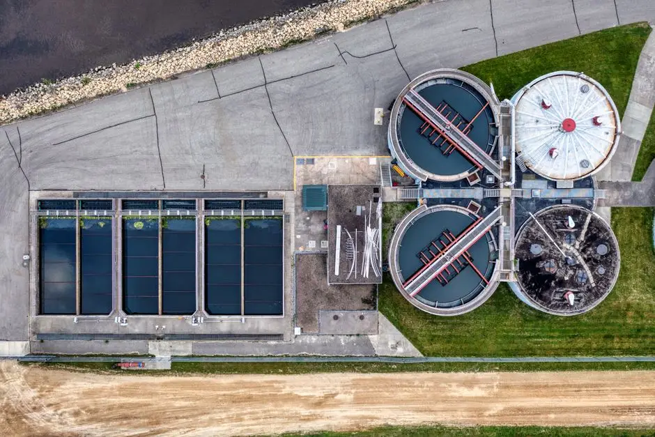
Wetted parts must be 2205 duplex or 316L stainless for E-stage service. Rubber-lined carbon steel is the cheaper spec on the quotation and the wrong spec for the operating envelope — rubber lining blisters at 70-80°C continuous service, and once the lining fails the carbon steel underneath loses 1-2 mm/year to general corrosion plus pitting under the blisters. The 30-50% stainless upcharge pays back in 3-4 years of avoided tank replacement, and the recycle pump, saturator, and air-compression side should be specified in the same alloy family.
The dissolved air flotation system covers 4-300 m³/h across 13 standard models with micro-bubble saturator, contact zone, separation zone, and automatic skimmer in a single skid — a configuration that fits the typical kraft ECF E-stage flow of 20-150 m³/h. Pre-floc DAF is the more common bleach-plant configuration because it lets a 2-3 minute upstream flocculation tube do the heavy lifting on chemistry and keeps the DAF cell focused on bubble-particle contact; post-floc DAF is reserved for streams that arrive already conditioned (e.g., the overflow from a kidney clarifier). Footprint for indoor mill installations runs 8-12 m² per m³/h of E-stage capacity, so a 50 m³/h unit lands in the 400-600 m² envelope including the chemistry skid and the float hopper.
| Configuration | Wetted Material | Footprint (m² per m³/h) | Indicative Service Life | Best-Fit Application |
|---|---|---|---|---|
| Rubber-lined carbon steel DAF | CS + rubber | 8-10 | 2-3 years at E-stage service | Not recommended for E-stage |
| 316L stainless DAF, pre-floc | 316L SS | 10-12 | 10-15 years | E-stage with upstream chemistry skid |
| 2205 duplex DAF, pre-floc | 2205 duplex | 10-12 | 15-20 years | E-stage with hot (70-80°C) feed |
| 2205 duplex DAF, post-floc | 2205 duplex | 10-12 | 15-20 years | E-stage overflow from kidney clarifier |
Frequently Asked Questions
Should DAF be placed before or after biotreatment for E-stage effluent?
Before biotreatment, every time. DAF removes TSS, colloids, and residual oxidant load that would otherwise shock the biology; placing DAF after biotreatment turns it into a polishing step that handles a far smaller, more uniform solids load but gives up the upstream process-change benefit flagged in the BioResources 2024 P&P review.
What sodium bisulfite dose is needed to quench hydrogen peroxide before DAF?
1.5-2.0× the stoichiometric H2O2 demand, with inline ORP control holding the residual below 5 mg/L H2O2 and 0.1 mg/L free chlorine. This is standard ECF practice and is the minimum to protect the DAF wetted parts and the downstream biology.
What micro-bubble diameter should be specified for alkaline E-stage filtrate?
10-50 µm at 4-6 bar saturation pressure, targeting 20-40 µm in operation. The Chemosphere 2024 flotation-mechanics work shows this band maximizes particle-bubble collision efficiency for the 5-100 µm colloid size distribution typical of E-stage filtrate.
What do the float solids from an E-stage DAF look like and how are they handled?
Brown, fibrous, 2-4% dry solids, smelling of residual peroxide and extractives. They are skimmed automatically, thickened, and dewatered on a plate and frame filter press to 30-35% cake, then sent to the bark boiler as fuel or to landfill depending on ash chemistry.
Can DAF alone meet PPER discharge limits for E-stage effluent?
No. DAF removes >85% of TSS and a meaningful fraction of COD, but BOD, AOX, and color remain — the BioResources 2024 review confirms that secondary biotreatment is required to meet the Canadian PPER BOD and acute-lethality limits. DAF is the load-reduction step, not the compliance step on its own.