Why White Water Is a Different MBBR Problem Than Municipal Graywater
White water is the clarified recirculation loop of a paper machine — the water that carries fines, fillers, starch, sizing agents, optical brighteners, and trace surfactant back through the headbox, screens, and cleaners. Compared to domestic graywater reviewed for MBBR reuse, white water runs dirtier and hotter. Typical envelopes from integrated pulp and paper operations sit at TSS 200–1,500 mg/L, COD 400–2,500 mg/L, and BOD 150–800 mg/L, with pH swinging between 4.5 and 8 depending on furnish and furnish additives, and temperature commonly 35–55 °C because the water leaves the dryer section warm. That temperature range shifts biofilm kinetics, doubling reaction rates roughly every 10 °C within the mesophilic window, which lets a compact MBBR outwork a municipal reactor of the same volume — but only if the engineer designs for the higher organic and fiber loading rather than copying a graywater template.
The other distinction is end use. Generic graywater MBBR studies (S3) target toilet flushing or irrigation; paper mill white water has two destinations, and they are not equivalent. Direct closure to machine showers and seal water requires tighter effluent than river discharge: lower TSS to protect nozzles, lower turbidity to keep optical brightener performance stable, and stable COD to avoid deposit formation on felts. A configuration sized for discharge compliance will not, on its own, meet reuse quality — which is why a side-by-side target table matters more in this service than in any municipal application.
How the MBBR Mechanism Handles White Water
Carriers in an MBBR are free-floating HDPE elements held inside the reactor by cylindrical sieves or grills on the outlet. The media have a density close to that of water, so gentle aeration keeps them in suspension without the high shear that would shear fragile biofilm from a packed-bed or RBC surface (per IJSR review, S2). For Kaldnes K1 and K3 media, the protected internal surface area typically falls in the 500–1,200 m²/m³ range, which is the design number an engineer uses to size reactor volume against a target BOD loading. That same density match is the reason MBBR suits low-shear white water service: the carriers do not need violent mixing to stay fluidized, so pump and blower energy stays modest.
Each carrier develops a stratified biofilm — an aerobic outer layer where heterotrophs and nitrifiers oxidize BOD and ammonia, and an anoxic core where denitrifying bacteria reduce nitrate to nitrogen gas. That structure is what makes staged anoxic-aerobic MBBR effective on the simultaneous BOD and nitrogen load of white water, without requiring a separate suspended-growth clarifier or sludge recycle loop. The MBBR vessel itself needs no backwash, no sludge return, and no clarifier inside the aerobic zone — biomass stays attached, and excess sloughs off with the effluent to be captured downstream if the engineer chooses. For a paper mill, that translates into a smaller tank farm, fewer rotating parts near a humid machine hall, and a biological step that tolerates the diurnal swings common when the paper machine changes grade.
Recommended MBBR Configuration: Two- or Three-Stage Staged Design
A two- or three-stage MBBR is the standard working configuration for paper mill white water. This includes an anoxic stage 1 for denitrification and starch hydrolysis, aerobic stage 2 for BOD and ammonia oxidation, and an optional aerobic stage 3 for residual polishing before reuse. Stage 1 anoxic HRT runs 2–3 h at MLVSS 2,000–3,500 mg/L on carriers, where facultative bacteria convert nitrate returned from stage 2 and begin breaking down the starch and sizing fractions that carry most of the slowly biodegradable COD. Stage 2 aerobic HRT runs 4–6 h at DO 2–3 mg/L and an F/M ratio of 0.15–0.30 kg BOD/kg MLVSS·d — a range typical of attached-growth nitrification designs where higher values risk oxygen limitation and lower values waste reactor volume. Where reuse is the target, stage 3 operates at lower volumetric loading (HRT 2–3 h, DO 2 mg/L) as a polishing buffer to stabilize effluent quality across grade changes on the paper machine.
Media selection is anchored to the surfactant-laden wastewater study at Universitas Tanjungpura (S1), which demonstrated strong COD, BOD, phosphate, and surfactant reduction on Kaldnes K1 at 20% volumetric fill. For higher-loaded white water, fill is scaled up to 40%, the upper bound commonly used in industrial MBBR practice to maximize attached biomass without short-circuiting flow through the bed. K1 carriers are retained by 5–7 mm sieve slot openings; K3, with its larger cross-section, requires roughly 10 mm. Aeration is supplied by coarse-bubble diffusers sized for 1.5–2.0 Nm³ air per m³ reactor volume per hour — a starting point the engineer tunes against measured DO profile rather than installing at face value. For a compact packaged skid that bundles the biological stage, see this integrated biological treatment package for a reference envelope of tankage, blowers, and carrier retention sieves.
| Parameter | Stage 1 Anoxic | Stage 2 Aerobic | Stage 3 Polishing (optional) |
|---|---|---|---|
| HRT (h) | 2–3 | 4–6 | 2–3 |
| DO (mg/L) | <0.5 | 2–3 | 2 |
| MLVSS on carriers (mg/L) | 2,000–3,500 | 3,000–5,000 | 3,000–4,500 |
| F/M (kg BOD/kg MLVSS·d) | — | 0.15–0.30 | 0.05–0.10 |
| Carrier fill (% vol) | 20–30 | 30–40 | 20–30 |
| Air supply (Nm³/m³·h) | — | 1.5–2.0 | 1.0–1.5 |
Pretreatment and Polishing: When to Add DAF, Screen, MBR, or RO
White water above 300 mg/L TSS will blind MBBR sieves and bury carrier surface area under a fiber mat within days. If the influent TSS sits consistently above 300 mg/L, install a upstream DAF unit or a rotary fine screen ahead of the MBBR. The DAF micro-bubble physics primer covers the 95%+ TSS removal envelope expected from a well-operated unit; in paper mill service, 60–85% TSS removal is realistic and is usually enough to bring white water inside the MBBR's comfort zone. For plants already running DAF for fiber recovery, the same vessel can double as MBBR feed protection with a chemistry adjustment.
Downstream of the MBBR, a clarifier is optional. Because MBBR carriers are retained by sieves, the only thing leaving the aerobic vessel is sloughed biofilm and residual fines, and a lamella or settling zone only earns its footprint if the engineer needs lower TSS for a strict discharge permit. For machine-shower reuse or zero-liquid-discharge schemes, an MBR polishing stage with submerged PVDF membranes at 0.1–0.4 μm cuts TSS to under 5 mg/L and turbidity under 1 NTU, which protects the RO membranes that follow. RO recovery on MBBR effluent typically lands at 70–85% — high enough to make a closed-loop design defensible, low enough that the concentrate stream still needs a treatment path. For an analogous packaged configuration on a different industrial wastewater, see the design notes on MBBR for solvent rinse water and MBBR for e-coat UF reject.
Reuse vs Discharge Effluent Targets: Side-by-Side Comparison
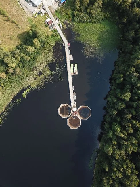
Reuse targets for paper machine showers and seal water are tighter than typical national discharge norms because particulates and residual COD foul nozzles, felts, and brightness-sensitive chemistries. The table below sets both bars side by side so a design engineer can size the train and the polish step in a single pass.
| Parameter | Reuse target (machine showers / seal water) | Discharge target (typical national norms) | MBBR-only achievable? |
|---|---|---|---|
| COD (mg/L) | ≤50 | 100–250 | Yes (discharge); reuse needs polish |
| BOD (mg/L) | ≤10 | ≤30 | Yes |
| TSS (mg/L) | ≤10 | ≤50 | Yes (discharge); reuse needs MBR |
| Turbidity (NTU) | ≤5 | — | No without MBR/RO |
| Total nitrogen (mg/L) | 10–15 | — | Only with anoxic stage; without it, 20–40 |
| Surfactant residual | Low (fiber/sizing protection) | Per local norm | Yes at 20% K1 fill (S1) |
Two practical conclusions fall out of this comparison. First, MBBR alone — staged anoxic + aerobic, sized to the table above — clears discharge limits on COD, BOD, and TSS for most jurisdictions, provided the engineer verifies the specific national norm governing the receiving water. Second, reuse to machine showers is not reachable without a downstream membrane step: an MBR to bring TSS and turbidity inside reuse spec, and an RO if the closure loop also targets boiler feed or high-pressure cleaning.
Operating Parameters and Monitoring Checklist
Daily checks include monitoring the DO profile across each stage (stage 1 below 0.5 mg/L, stage 2 at 2–3 mg/L, stage 3 at 2 mg/L), pH held in the 6.5–8.0 band, reactor temperature, and a visual pass over the sieve to confirm carrier fill is intact and no matting has formed at the waterline. Weekly: F/M ratio back-calculated from influent BOD and attached MLVSS via a carrier-scraping test, and surfactant residual where the furnish carries wet-strength or deinking chemistry. Quarterly: sieve inspection for slot wear, carrier breakage count against a baseline (typical wear is below 2% of inventory per year for K1/K3 HDPE in mechanical-mix service), and coarse-bubble diffuser head pressure to catch fouling before it starves the aerobic stage.
Triggers for media top-up include visible carrier loss across the outlet sieve even after the sieve is clean, or a steady decline in BOD or ammonia removal with influent quality unchanged. A carrier inventory check at every quarterly turnaround — count a representative sample, compute percent breakage, and reorder when the working fill drops more than 5 percentage points below design.
Frequently Asked Questions
What carrier fill percentage should I specify for paper mill white water?
Specify 20–40% volumetric Kaldnes K1 or K3 HDPE fill. The 20% K1 anchor comes from the surfactant-wastewater MBBR study at Universitas Tanjungpura (S1), which demonstrated effective COD, BOD, phosphate, and surfactant reduction at that fill; scale toward 40% on higher-loaded white water or when adding polishing capacity.
What HRT and DO setpoints run a two-stage MBBR on white water?
Stage 1 anoxic HRT 2–3 h at DO below 0.5 mg/L; stage 2 aerobic HRT 4–6 h at DO 2–3 mg/L, F/M 0.15–0.30 kg BOD/kg MLVSS·d. Add a stage 3 aerobic polish (HRT 2–3 h) if the effluent targets reuse rather than discharge.
Can MBBR alone meet reuse targets for paper machine showers