Why E-Coat UF Reject Is a Different Wastewater
UF reject from a cationic electrodeposition (e-coat) line is the concentrated retentate left behind when the ultrafiltration loop recovers paint solids from the rinse overflow. That distinction governs everything in the downstream biological stage. The reject carries 3,000–8,000 mg/L COD, 500–2,000 mg/L TSS (mostly uncrosslinked epoxy resin, pigment, and surfactant), a BOD/COD ratio of only 0.25–0.45, and a C:N:P ratio that is carbon-rich and nutrient-starved (HydropureWater field data, 2026). After UF concentration cycles, pH commonly drifts to 5.5–7.0, and shift-end wash events inject intermittent spikes of glycol ethers and amines.
The stoichiometry is the problem a generic MBBR spec cannot solve. A single biofilm reactor exposed to COD >5,000 mg/L with BOD:N well below the 100:5 ratio required for nitrification will favor heterotrophic growth on the carrier surface, suppress nitrifier colonization, and shed biofilm when solvent spikes arrive. The low BOD:N ratio also means a single stage cannot simultaneously oxidize the bulk COD and nitrify amine nitrogen — the two populations compete for the same surface area. A staged configuration is the engineering answer, not an upgrade.
Reference MBBR-MBR Configuration for Reuse-Grade Effluent
The UPC 2021 hybrid study by Yang at INTEXTER (Universitat Politècnica de Catalunya, Terrassa) evaluated MBBR followed by MBR for textile industrial effluent (source: upcommons.upc.edu, 2021-05). The textile analogy is appropriate: both streams carry high organic load, color bodies, and surfactant residues, and both require closed-loop reuse-quality water for process make-up. The study concluded that MBBR-treated water reused in new dyeing processes met textile-industry quality acceptance limits — the same closed-loop logic a tier-1 coater applies to a deionized rinse loop.
The economic finding matters as much as the process result. The Yang thesis reports that MBBR-MBR delivered lower CAPEX and OPEX than a conventional activated-sludge (CAS) system, driven by lower effluent discharge tax and reduced decolorizing-agent demand (per-m³ operating cost tables IV-4 and VII-3 in the thesis). For an automotive coater weighing a biological stage upgrade, the reuse-grade configuration is the cheaper option over a 10-year horizon, because the avoided water purchase and sewer surcharge dominate the membrane OPEX.
Two-Stage MBBR Process Train: Stage-by-Stage Specification
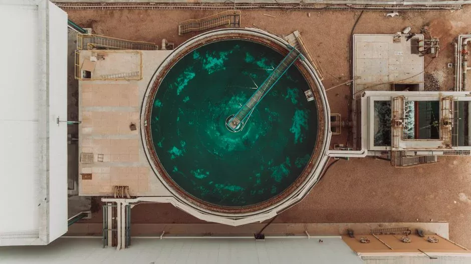
A two-stage MBBR in series is the standard configuration for e-coat UF reject, utilizing Stage 1 roughing at 50–60% carrier fill for high-COD paint load and Stage 2 polishing at 30–40% fill with controlled DO 2–4 mg/L and supplemental carbon/nutrient balancing. The staging is not redundant: Stage 1 absorbs the bulk COD shock and protects Stage 2's nitrifying biofilm from solvent sloughing. Below is the step-by-step process flow an engineer can lift into an RFQ.
- Influent screening — coarse and fine screens to remove cured paint chips and rags from the UF reject sump.
- Paint solids removal — a DAF system for paint solids removal or a lamella clarifier for MBBR feed polishing drops TSS below ~200 mg/L before the biological stage.
- Equalization + pH trim — 12–24 h basin, NaOH dosing to lift pH into the 6.5–7.5 range.
- Stage 1 MBBR (roughing) — 50–60% HDPE carrier fill (specific surface 500–700 m²/m³), HRT 8–14 h, DO 1.5–2.5 mg/L, surface loading 6–10 g BOD/m²·d; target 60–75% COD removal.
- Inter-stage nutrient dosing — urea and phosphoric acid injection on the Stage 1 → Stage 2 line, lifting BOD:N:P toward 100:5:1.
- Stage 2 MBBR (polishing) — 30–40% carrier fill, HRT 4–8 h, DO 2–4 mg/L, surface loading 1.5–3 g BOD/m²·d; target residual COD <300–500 mg/L.
- MBR or UF polish — required for reuse routes; submerged PVDF flat-sheet or hollow-fiber membrane at 0.1–0.4 µm.
- Carbon polish / RO — required only for closed-loop DI-grade reuse.
Stage 1 runs deliberately under-aerated (DO 1.5–2.5 mg/L) to favor heterotrophic biofilm and prevent excess endogenous decay that would otherwise strip carbon before Stage 2's nitrifiers see it. Stage 2 raises DO to 2–4 mg/L to give nitrifiers the oxygen gradient they need at low residual BOD. The nutrient trim between stages is the most common reason a Stage 2 reactor fails to establish stable nitrification.
MBBR Stage Parameters at a Glance
The following engineering datasheet provides operational ranges drawn from HydropureWater e-coat field installations (2025–2026) and cross-checked against MBBR design manuals for high-COD industrial streams.
| Stage | Carrier fill (%) | Specific surface area (m²/m³) | HRT (h) | DO (mg/L) | BOD surface load (g/m²·d) | Target COD removal |
|---|---|---|---|---|---|---|
| Stage 1 — Roughing | 50–60 | 500–700 | 8–14 | 1.5–2.5 | 6–10 | 60–75% |
| Stage 2 — Polishing | 30–40 | 500–700 | 4–8 | 2–4 | 1.5–3 | Residual COD <300–500 mg/L |
| Stage 3 — Re-aeration (optional, surface-water discharge only) | 20–30 | 500–700 | 2–4 | 3–5 | <1 | Sludge stabilization, residual NH₃ polishing |
Stage 3 is only necessary when the receiving water is sensitive (low-flow surface water with strict ammonia targets, typically <1–2 mg/L NH₃-N). For a municipal sewer discharge, two stages plus a lamella clarifier is the typical installed configuration.
Pretreatment Before the MBBR Stages
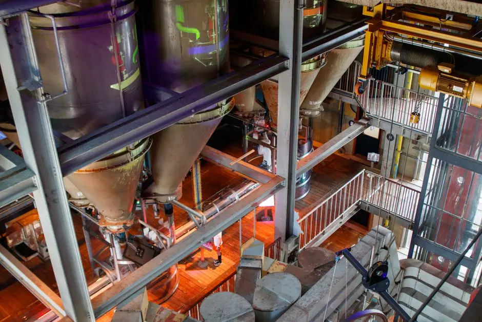
Paint solids are the primary contaminant that causes biofilm failure in MBBR systems. Uncrosslinked epoxy resin plates onto the carrier media, blocks the protected surface area, and triggers sloughing events that wash biomass into Stage 2. The upstream train must perform four functions in order. First, a DAF system for paint solids removal (or lamella clarifier) drops TSS below ~200 mg/L entering Stage 1. Second, pH adjustment to 6.5–7.5 is required, as e-coat UF reject commonly sits at 5.5–6.5 and biofilms below pH 6.0 nitrify poorly. Third, an equalization basin sized for 12–24 h HRT buffers the shift-end solvent and detergent spikes. Fourth, nutrient dosing (urea + phosphoric acid) on the equalization transfer line lifts BOD:N:P toward 100:5:1.
The same logic applies to other concentrated metal-finishing streams — the MBBR pretreatment for passivation chrome rinse follows an identical head-of-line architecture (oxidation-reduction → solids removal → pH/equalization → biological). Skipping pretreatment in e-coat duty typically causes biofilm sloughing within 2–4 weeks of startup, bulking in Stage 2, and rapid MBR membrane blinding.
Reuse vs Discharge: Choosing the Right End-of-Pipe
The reuse-vs-discharge decision maps to a specific end-of-pipe configuration based on target effluent quality. The decision table below provides the routing rules for a P&ID.
| Discharge / reuse target | Required configuration | Typical effluent quality |
|---|---|---|
| Municipal sewer (conventional limits, e.g. COD <500–800 mg/L, TSS <200 mg/L) | Two-stage MBBR + lamella clarifier | COD 300–500 mg/L, TSS <100 mg/L, no NH₃-N guarantee |
| Surface water (strict BOD/COD/SS, EPA industrial surface water discharge) | Two-stage MBBR + MBR polishing after the MBBR stages (submerged PVDF 0.1–0.4 µm) | COD <100 mg/L, TSS <5 mg/L, NH₃-N <2 mg/L |
| Closed-loop rinse make-up (DI-grade reuse, low conductivity) | Two-stage MBBR + MBR + RO (with carbon polish) | Conductivity <50 µS/cm, TOC <5 mg/L, no surfactants |
The membrane modules for the reuse case use a DF-series flat-sheet MBR module rated for the surfactant and solvent residual that survives Stage 2. MBR alone delivers <1 µm filtrate but cannot strip conductivity or residual low-MW organics — that is the job of the RO pass. MBBR-MBR remains the lower-CAPEX/OPEX configuration for the reuse route because avoided water purchase costs dominate the membrane OPEX over a 10-year horizon.
Frequently Asked Questions
How many MBBR stages are required to treat e-coat UF reject? Two stages in series — a 50–60% fill roughing reactor followed by a 30–40% fill polishing reactor — is the standard configuration for COD 3,000–8,000 mg/L reject (HydropureWater field data, 2026).
Can a single-stage MBBR handle e-coat UF reject? No. A single stage cannot simultaneously remove bulk COD and nitrify amine nitrogen at the BOD:N ratio present in UF reject; biofilm competition between heterotrophs and nitrifiers will collapse Stage 2 performance.
Is MBR always required downstream of the MBBR? Only for surface-water discharge or reuse. For municipal sewer discharge, a two-stage MBBR plus lamella clarifier is typically sufficient to meet COD <500–800 mg/L limits.
When is RO necessary in the polishing train? RO is required only for closed-loop DI-grade rinse reuse, where conductivity must drop below ~50 µS/cm and residual low-MW organics must be stripped; MBR alone cannot achieve either.
How is waste activated sludge from the MBBR stages handled? Sloughed biofilm from Stage 1 and 2 is captured on the downstream lamella or MBR membrane, dewatered by a belt press or decanter centrifuge, and disposed as paint-contaminated industrial waste — typically D-classified.