Why Desalter Brine Dilute Is Not Generic Oily Water
Desalter brine dilute is a refinery-specific stream that sits between the electrostatic desalter and downstream sour-water stripping or biological treatment, and its chemistry drives DAF design choices differently from generic oily wastewater. Typical industry ranges for the aqueous phase separated from the desalter wash-water circuit are 50–500 mg/L emulsified oil, 100–500 mg/L TSS, 30–60 °C, and 1,000–5,000 mg/L TDS — not the trace oil loadings of a general refinery process water stream.
Residual chemical demulsifier and the high salt background stabilize the oil-in-water emulsion, which is why gravity separation and API/CPI alone rarely meet reuse or discharge targets. DAF fills that gap: among flotation technologies including electrolytic and dispersed-air flotation, DAF has been the most commonly used in industrial wastewater settings (MDPI Processes, 2020), and the DAF cell here acts as a polishing/equalization step, not as bulk oil removal.
| Parameter | Typical Range for Desalter Brine Dilute | Design Implication |
|---|---|---|
| Emulsified oil | 50–500 mg/L | Micro-bubble flotation required; CPI insufficient |
| Total suspended solids | 100–500 mg/L | Skim layer 2–5% dry solids — sludge handling needed |
| Temperature | 30–60 °C | Saturator must tolerate >50 °C or stream must be cooled |
| Total dissolved solids | 1,000–5,000 mg/L | High ionic strength stabilizes emulsion; coagulant demand rises |
| Chemical demulsifier carryover | Variable, persistent | Breaks gravity separation; favors DAF with polymer conditioning |
How DAF Actually Treats Desalter Brine Dilute
DAF removes emulsified oil and suspended solids by attaching micro-bubbles to destabilized droplets and floating the agglomerates to the surface for skimming. This four-step mechanism maps directly to the design parameters an engineer can tune.
The sequence is: (1) coagulation/flocculation of the emulsified oil with cationic coagulant and anionic flocculant, (2) pressurized air–water saturation in a saturator at 4–6 bar, (3) controlled release through needle valves or eductor nozzles that nucleate a cloud of micro-bubbles, and (4) skimming of the buoyant float layer into a scum trough while clarified effluent flows out the bottom. Compared with conventional sedimentation, DAF delivers rapid output, a high loading rate, and low hydraulic retention time (MDPI Processes, 2020), fitting the equalization/polishing slot between primary separation and biotreatment.
Micro-bubble size is the mechanism's heart. Bubbles in the 10–60 μm range have a high surface-area-to-volume ratio, attach readily to oil droplets in the 5–50 μm band, and lift them at terminal rise velocities of 20–100 m/h — this is the standard industry micro-bubble sizing band for oil removal on high-rate DAF units. Saturation efficiency then governs capture: dissolved-air mass per cubic meter of recycle sets the air-to-solids ratio (A/S), which for refinery dilute brines typically runs 0.02–0.10 g air per g oil. A dissolved air flotation (DAF) system sized to this envelope will hit the ≤50 mg/L O&G and <30 mg/L TSS targets the engineer is buying it for.
Core DAF Design Parameters for Brine Dilute Treatment
Engineers specify the following dial-settings on a data sheet or audit them during a factory acceptance test. These are stated as standard industry values because the available research corpus is generic rather than desalter-specific.
Hydraulic loading rate sits at 15–25 m/h for high-rate DAF in oily refinery service — high enough to make the footprint economical, low enough to keep bubble–droplet contact time realistic. Recycle ratio is 20–50% of treated effluent recirculated through the saturator; pushing it higher improves bubble density and oil capture but cuts net throughput and inflates pump and compressor power. Micro-bubble size from the release valve or eductor should be 10–60 μm — smaller is better for emulsified oil because the bubble has to be smaller than the droplet it lifts, but smaller bubbles also mean higher pressure drop across the nozzle and more dissolved-air pump work. Coagulant pairing is cationic polyaluminum chloride (PAC) at 20–80 mg/L followed by anionic flocculant at 0.5–3 mg/L; brine's high TDS compresses the electrical double layer, so dose tuning against jar tests is non-negotiable. Saturator pressure of 4–6 bar with 60–90% air dissolution and operating temperature tolerance up to 60 °C covers the 30–60 °C feed band without derating.
| Parameter | Design Range | Notes / Trade-off |
|---|---|---|
| Hydraulic loading rate | 15–25 m/h | Higher = smaller footprint, shorter contact time |
| Recycle ratio | 20–50% | Higher = better capture, lower throughput |
| Micro-bubble size | 10–60 μm | Smaller = better on emulsions, more compressor load |
| Saturator pressure | 4–6 bar | Sets dissolved-air mass per m³ recycle |
| Air-to-solids ratio (A/S) | 0.02–0.10 g air/g oil | Governs oil-droplet capture |
| PAC dose | 20–80 mg/L | Cationic; jar-test against feed |
| Anionic flocculant dose | 0.5–3 mg/L | Builds floc size for bubble attachment |
| Operating temperature | Up to 60 °C | Matches 30–60 °C feed; consider cooling for reuse |
Reuse vs Discharge: Which Configuration Do You Buy?
The choice between reuse and discharge dictates whether a single DAF is sufficient or if downstream polishing is mandatory. Selecting the wrong train can result in fouling the desalter's electrostatic grid or overspending on unnecessary filtration.
If the goal is reuse as desalter wash-water make-up, the DAF must polish to ≤20 mg/L O&G and <30 mg/L TSS. A single-stage high-rate DAF is usually insufficient on its own at the dirty end of the feed range — pair it with a polishing multi-media filter or sand filter to protect the desalter's electrostatic grid from residual oil-wet solids. If the goal is discharge, the DAF effluent only needs to meet the SOG threshold below 50 mg/L (MDPI Processes, 2020) and then route to downstream biotreatment; a single-stage dissolved air flotation (DAF) system with coagulant dosing is generally adequate. Two-stage DAF is a middle path for sites with intermittent feed upsets or tighter discharge consent than the standard 50 mg/L SOG ceiling.
Heat management is a side constraint on the reuse path: brine leaving the desalter at 50–60 °C should pass through a cooling step (plate heat exchanger or cooling tower loop) before the DAF so the saturator runs below 50 °C, where Henry's-law air solubility is more predictable and bubble formation stays stable.
| Configuration | Target O&G / TSS | Footprint | CAPEX Order | Reuse-Eligible? |
|---|---|---|---|---|
| Single-stage DAF + coagulant | ≤50 / <30 mg/L | Smallest | 1× | No (not consistently) |
| Two-stage DAF + coagulant | ≤30 / <20 mg/L | ~1.6× single stage | ~1.7× | Marginal |
| Single-stage DAF + multimedia filter | ≤20 / <10 mg/L | ~1.4× single stage | ~1.5× | Yes |
| Two-stage DAF + multimedia filter + UF | ≤10 / <5 mg/L | Largest | ~2.5× | Yes (closed loop) |
Integration With the Rest of the Refinery Water Train
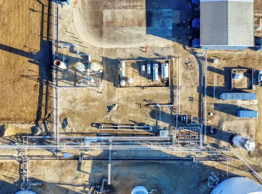
DAF must be integrated between upstream separation, chemical conditioning, sludge handling, and downstream polish. Incorrect interfaces can cause the cell to choke on unemulsified oil or dump a stable emulsion into biotreatment.
Position the DAF as a tertiary equalization step after primary gravity separation (API or CPI separator) and before biotreatment; DAF is operable at primary, secondary, or tertiary stages depending on feed (MDPI Processes, 2020), and for desalter brine dilute the tertiary slot is the correct choice. Upstream, an automatic coagulant and polymer dosing skid is required to destabilize the emulsion before the feed enters the DAF cell — manual dosing cannot hold the 20–80 mg/L PAC band against a feed that swings with desalter performance. Downstream of the DAF, floated scum at 2–5% dry solids needs dewatering; a plate-and-frame filter press is the standard choice to cut disposal volume before the skim goes to a sludge thickener or off-site incinerator. For reuse loops, finish the train with a multi-media filter or ultrafiltration stage ahead of the desalter wash-water tank to keep residual solids out of the desalter's mixing system — a useful parallel to the design logic in DAF configuration for solvent stripper dilute water, which faces the same reuse-versus-discharge decision against a different feed profile, and worth reading alongside a buy-side comparison of DAF oil-water separators if you are shortlisting vendors. Refineries running fluoride-bearing streams will also recognize the same equalization-then-DAF logic in refinery hydrofluoric acid wastewater treatment hybrid systems.
Frequently Asked Questions
What DAF configuration treats desalter brine dilute for reuse or discharge?
A high-rate micro-bubble DAF at 15–25 m/h hydraulic loading, 20–50% recycle, and 10–60 μm bubble size, paired with 20–80 mg/L PAC and 0.5–3 mg/L anionic flocculant, reliably hits ≤50 mg/L O&G and <30 mg/L TSS — adequate for discharge below the 50 mg/L SOG limit (MDPI Processes, 2020), with a multimedia polish filter added when the stream is recycled to desalter wash water.
Can a single-stage DAF handle the full 50–500 mg/L oil range in desalter brine dilute?
At the low end (50–150 mg/L) a single-stage DAF with proper coagulant
Frequently Asked Questions
What DAF configuration treats desalter brine dilute for reuse or discharge?
A high-rate Dissolved Air Flotation (DAF) system configured with a saturation vessel, a recycle pump, and a chemical coagulation/flocculation pretreatment stage is required. For desalter brine, a rectangular DAF unit with a hydraulic loading rate between 4 and 8 gpm/ft² is typically employed to ensure sufficient residence time for emulsified oil removal.
What recycle ratio and bubble size are best for refinery brine DAF?
The optimal recycle ratio for desalter brine typically ranges from 10% to 30% of the influent flow, with saturation pressures maintained between 50 and 100 psi. To effectively attach to oil droplets, bubble sizes should be maintained in the 10 to 100 micron range, ensuring a high surface-area-to-volume ratio for maximum flotation efficiency.
Can DAF effluent from desalter brine be reused as desalter wash water?
Yes, DAF effluent can be reused as wash water provided the Total Suspended Solids (TSS) are below 20 mg/L and oil content is reduced to under 10-15 mg/L. This closed-loop configuration reduces freshwater intake and minimizes the volume of brine sent to the wastewater treatment plant.
What oil and grease level should a DAF achieve for refinery discharge?
For direct discharge to municipal sewers or environmental water bodies, DAF systems must typically reduce Oil and Grease (O&G) concentrations to below 15 mg/L, though many stringent 2026 regulatory standards target levels below 5 mg/L. Achieving these levels often requires the addition of cationic polymers to destabilize remaining emulsions.
How does DAF compare to API/CPI separators for desalter brine polishing?
Unlike API separators, which rely on Stokes' Law and buoyancy for droplets >150 microns, or CPI units targeting >20 microns, DAF can remove emulsified oil droplets down to 2-5 microns. DAF is significantly more effective for polishing desalter brine because it actively increases the buoyancy of small droplets via micro-bubble attachment, whereas API/CPI systems are primarily for primary bulk oil recovery.