
Why Reactive Dyeing Bath Dump Breaks Conventional Treatment
Reactive dye bath dump streams carry 50–100 g/L NaCl or Na2SO4 from the salt-driven exhaustion step, exit the dye machine at 60–90 °C, and are dominated by hydrolysed reactive dye — a non-fixable, chromatically persistent fraction that resists both adsorption and oxidation. The BOD/COD ratio routinely sits below 0.2 because the carbon is largely dye-bound rather than auxiliaries, and pH swings from 8 to 11 across the rinse cascade. A conventional activated sludge plant operated at the 2–4 g/L MLSS typical of municipal biology collapses on three fronts: salt shock inhibits heterotrophs above 10–15 g/L TDS, the 60–90 °C thermal pulse strips floc and crashes settleability, and the hydrolysed dye chromophore passes straight through the clarifier. An MBR decouples SRT from HRT — biomass retention can be pushed to 30–60 days at 6–8 g/L MLSS while the hydraulic residence is held at 6–8 h — so colour-degrading consortia and salt-acclimated biomass stay in the tank long enough to act on a substrate that conventional biology simply washes out. The MBR permeate also exits at sub-1 NTU turbidity and near-zero TSS, which is the only effluent quality a downstream RO or NF can accept without rapid fouling. For a 2026 dye house weighing capital spend against a reuse or discharge obligation, MBR is the configuration that makes the downstream train possible — not an upgrade, but a prerequisite. A full textile wastewater recycling system design starts from this premise.
Submerged vs Sidestream vs Tubular MBR: Configuration Comparison
Three MBR configurations compete for a reactive dye bath duty, and the choice is driven by influent character rather than membrane cost. Submerged flat-sheet PVDF modules (0.1–0.4 µm pore, integrated aeration scouring at 8–12 m³ air per m² membrane area per hour) sit inside the aeration tank and rely on rising bubbles for cross-flow. They draw 0.1–0.3 kWh per m³ permeate, roughly 10–20× less than an external cross-flow loop (HydropureWater DF-series module data, 2026), but tolerate only moderate TSS (≤10–12 g/L) and temperatures held below 40 °C. Sidestream hollow-fiber units pump mixed liquor through an external pressure vessel at 0.5–3 m/s cross-flow velocity — the high shear keeps TSS up to 15–18 g/L manageable, but energy climbs to 2–4 kWh/m³ and fibre integrity is vulnerable to hotspot excursions. Tubular MBR uses 8–25 mm diameter channels operated at 1–3 m/s with MLSS of 8–12 g/L; it is the only configuration that can take a 70 °C slug load and a fibre-laden dump without blinding, and it is the architecture Sun et al. (2010, doi 10.5539/mas.v4n2p41) validated on real printing and dyeing wastewater, reporting 82% COD removal and 80% chroma removal at MLSS 8 g/L and HRT 8 h with PAC coagulation upstream. The energy penalty for that robustness is real: tubular MBR consumes 1.5–3 kWh/m³ versus 0.1–0.3 kWh/m³ for a flat-sheet module (HydropureWater field data, 2026), so the configuration decision is a question of how much thermal and fibre shock the upstream equalisation can remove. An integrated submerged MBR system is the right default; a submerged flat-sheet PVDF membrane module is the specific hardware most dye houses buy for the duty once temperature and fibres are tamed.
| Parameter | Submerged flat-sheet PVDF | Sidestream hollow-fiber | Tubular MBR |
|---|---|---|---|
| Pore size / geometry | 0.1–0.4 µm flat sheet | 0.03–0.1 µm hollow fibre | 0.05–0.2 µm tube, 8–25 mm ID |
| MLSS operating range | 6–10 g/L | 8–15 g/L | 8–12 g/L (Sun et al. 2010: 8 g/L) |
| HRT | 6–8 h | 4–8 h | 8 h (Sun et al. 2010) |
| Cross-flow / scouring | Integrated aeration, 8–12 m³/m²·h | 0.5–3 m/s pump loop | 1–3 m/s recirculation |
| Specific energy demand | 0.1–0.3 kWh/m³ | 2–4 kWh/m³ | 1.5–3 kWh/m³ |
| Influent temperature ceiling | <40 °C | <45 °C | 70–80 °C short-term |
| Dominant fouling mode | Biofouling, cake layer | Fibre clogging, scaling | Particulate and fibrous blinding |
| Footprint per m³/d | Low (membrane in tank) | Medium (external skid) | High (large channel area) |
| COD removal (Sun et al. 2010 train) | 70–78% typical | 75–82% | 82% |
| Chroma removal (Sun et al. 2010 train) | 65–75% typical | 70–80% | 80% |
Recommended Pre-Treatment Train for Reactive Dye Bath
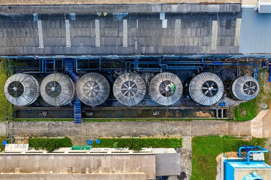
The MBR is only as good as what it sees, and for a reactive dye bath the upstream sequence is non-negotiable. Polyaluminium chloride (PAC) at 50–150 mg/L is the best coagulant for reactive dye colour reduction — Sun et al. (2010) screened PAC against alum, polyacrylamide, and ferric chloride and found PAC removed 60–70% of colour at optimal dose, compared with 30–45% for ferric and 25–40% for alum on the same printing and dyeing feed. The mechanism is charge neutralisation plus enmeshment of the anionic sulphonated dye groups. After coagulation, a dissolved air flotation pre-treatment stage lifts the coagulated sludge before the biological step, protecting the membrane from particulate loading. Hydrolytic acidification follows: it lifts the BOD/COD ratio from below 0.2 toward 0.3–0.4 by breaking dye auxiliaries into short-chain organic acids, giving the MBR biomass a substrate it can actually metabolise rather than the recalcitrant chromophore alone. Equalisation must drop the 60–90 °C dump to below 40 °C — PVDF membranes and mesophilic biology both lose performance rapidly above 45 °C — and an upstream fibre screen (0.5–1 mm aperture) catches the loose cotton lint that would otherwise mat the flat-sheet panels. An automatic PAC coagulant dosing skid ties the dose to flow-proportional signals so the coagulant tracks the dump cadence rather than a fixed timer.
Operating Envelope and Expected Effluent Quality
The 2026 operating window an engineer should write into a reactive dye bath MBR specification is narrow. MLSS 6–8 g/L, HRT 6–8 h, DO 2–3 mg/L at the membrane tank, pH 6.5–7.5, SRT 30–60 days, and temperature held below 40 °C at the membrane module are the values that match the Sun et al. (2010) pilot envelope while leaving headroom for slug loads. The reference train on real printing and dyeing wastewater delivered 82% COD removal and 80% chroma removal in a single pass — useful numbers, but they are discharge-oriented, not reuse-grade. MBR permeate typically exits at TSS below the detection limit (the membrane is the solid-liquid separator), turbidity under 1 NTU, COD in the 60–120 mg/L window, and residual colour still measurable in Pt-Co units, which is precisely why a reuse train adds NF or RO downstream. The 2026 compliance targets the engineer is measured against are the China GB 4287-2012 discharge limits (COD ≤ 80 mg/L for direct discharge to surface water in existing enterprises, ≤ 200 mg/L for the indirect-discharge tier to a municipal sewer, chromaticity dilution倍数 ≤ 40), the EU BREF textile effluent values (COD 125–160 mg/L, colour visible absence), and the ZDHC Wastewater Guidelines (COD ≤ 150 mg/L, colour as Δ absorbance at 436/525/620 nm within defined limits). MBR meets the indirect-discharge tier comfortably and the direct-discharge tier on COD, but residual chroma is the gap an NF or RO closes. The same hardware — an integrated submerged MBR system — sits underneath either compliance path.
| Parameter | Reactive dye bath influent | MBR effluent (Sun et al. 2010 train) | Discharge target (GB 4287-2012) | Reuse target (NF/RO permeate) |
|---|---|---|---|---|
| COD (mg/L) | 800–1,500 | 140–270 (~82% removal) | ≤ 80 (direct) / ≤ 200 (indirect) | < 25 |
| BOD (mg/L) | 80–200 | 10–30 | ≤ 20 (direct) | < 5 |
| Colour (dilution倍数 / Pt-Co) | 500–2,000× | 100–400× (~80% removal) | ≤ 40× | < 5× (ND) |
| TSS (mg/L) | 200–800 | < 5 | ≤ 50 | < 1 |
| TDS / salinity (g/L NaCl) | 30–80 | 30–80 (unchanged) | No salt limit at discharge; ZDHC TDS ≤ 2,000 mg/L for reuse | < 0.5 |
| Temperature (°C) | 60–90 | < 40 (post equalisation) | ≤ 40 at outfall | Ambient |
| pH | 8–11 | 6.5–7.5 | 6–9 | 6.5–8.5 |
From MBR to Reuse: Adding Nanofiltration or RO
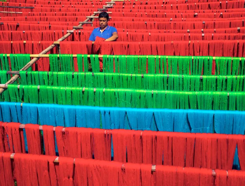
MBR permeate is clean water with salt and residual colour still in it — fit for sewer discharge in most jurisdictions, but a long way from a reuse-grade wash-off stream. The Springer 2024 chapter Sustainable Wastewater Reuse with Membrane Bioreactor (MBR) Technology in the Textile Industries (doi 10.1007/978-3-031-62054-6_15) flags MBR + NF hybrid trains as the open research question for high water recovery in textile reuse, and documents pilot-scale studies where the MBR protected the NF from organic fouling, pushing recovery to 80–90%. The choice between NF and RO is a water-salt balance: nanofiltration removes 95–99% of divalent salts and the chromophore-carrying dye molecules but lets 20–40% of NaCl pass, recovering 75–85% of the feed at 0.4–0.7 kWh/m³; an industrial RO system for reuse polishing gives 98–99.5% NaCl rejection at 90–95% recovery but pulls 0.8–1.5 kWh/m³ and needs higher pressure (10–25 bar for BWRO). For a dye house whose wash-off water must be near-zero TDS, RO is the only honest answer; for one blending reuse with a fresh-water dilution, NF is often the better economic compromise. The concentrate stream — 10–25% of the NF/RO feed — is the real operating cost, because it still carries the rejected salt and colour and has to go to a salt-tolerant disposal route. A 2026 reuse train is sized as MBR + NF/RO end to end, not as MBR with a future upgrade in mind.
Decision Framework: Which MBR Configuration for Your Reactive Dye Bath
Procurement needs a rule, not a comparison. Four rules cover the 2026 duty. Rule 1: Default to a submerged flat-sheet PVDF MBR if the dye house can equalise temperature to under 40 °C and pre-coagulate with PAC — this is the lowest energy and smallest footprint option and the workhorse of any MBR + NF/RO reuse train. Rule 2: Pick tubular MBR if the influent arrives at 60–80 °C peaks, carries visible cotton fibre, or comes in slug dumps that would blind a flat-sheet panel within hours — the Sun et al. (2010) reference train is exactly this architecture. Rule 3: Pick sidestream cross-flow only when MBR-tank TSS routinely exceeds 12–15 g/L and a retrofit into an existing high-shear pump loop is preferred over a greenfield tank redesign. Rule 4: If the target is reuse rather than discharge, specify MBR + NF/RO as a single train from day one — sizing the MBR for the downstream membrane's recovery and fouling envelope is cheaper than retrofitting later, because the MBR's COD, TSS, and chroma targets move depending on whether NF or RO follows. The full MBR vs SBR comparison is the reference document for the upstream biological choice; this guide is the MBR-side selection.
| Influent character | Recommended MBR configuration | Pre-treatment must-haves | Downstream polishing |
|---|---|---|---|
| Cooled (<40 °C), low-fibre, COD < 1,200 mg/L | Submerged flat-sheet PVDF, MLSS 6–8 g/L, HRT 6–8 h | PAC coagulation + DAF + equalisation | NF (75–85% recovery) for blended reuse |
| Hot slug loads (60–80 °C), fibre-bearing | Tubular MBR, MLSS 8 g/L, HRT 8 h (Sun et al. 2010) | Fibre screen + PAC + hydrolytic acidification + cooling | BWRO for reuse; sewer for discharge |
| High TSS (12–15 g/L), retrofit duty | Sidestream hollow-fiber, external cross-flow | DAF + screening + cooling | NF or RO depending on TDS target |
| Reuse-grade target from day one | Submerged flat-sheet MBR sized to feed NF/RO at 80–90% recovery | PAC + hydrolytic acidification + cooling + fibre removal | RO for TDS < 0.5 g/L reuse |
Frequently Asked Questions
What is the best MBR configuration for reactive dye bath effluent in 2026? A submerged flat-sheet PVDF MBR preceded by PAC coagulation and hydrolytic acidification, operating at MLSS 6–8 g/L and HRT 6–8 h, is the lowest-energy default for a 2026 reuse train (HydropureWater field data, 2026). Tubular MBR is the fallback when influent temperatures exceed 60 °C or loose fibre loads would blind a flat-sheet module.
How much COD and colour can an MBR remove from reactive dye bath effluent? A tubular MBR on real printing and dyeing wastewater achieved 82% COD removal and 80% chroma removal at MLSS 8 g/L and HRT 8 h with PAC coagulation upstream (Sun et al., 2010, doi 10.5539/mas.v4n2p41). These are single-pass values; reuse requires an NF or RO polish to clear residual chroma and TDS.
Can MBR handle high salinity from reactive dye fixation wash-off? Salt-tolerant biomass acclimated at 30–60 day SRT tolerates 30–80 g/L TDS in the MBR tank, but the MBR does not reject salt — NaCl passes through into the permeate. Salt management is a downstream RO or NF question, not an MBR question.
Is MBR alone enough to meet China GB 4287-2012 discharge limits? MBR effluent typically meets the GB 4287-2012 indirect-discharge tier (COD ≤ 200 mg/L, chromaticity ≤ 80×) reliably and the direct-discharge COD tier (≤ 80 mg/L) on most feeds, but residual colour often exceeds the 40× direct-discharge chromaticity limit without downstream polishing.