What a UV Transmittance Sensor Does in a Disinfection System
A UV transmittance sensor for disinfection is an online optical probe that measures the fraction of UV-C light — almost always at 254 nm — passing through a 1 cm water column, reported as %UVT/cm. The reading feeds the UV ballast control loop, which automatically raises or lowers lamp power to hold a validated dose of 30–40 mJ/cm² for fecal coliform and E. coli compliance in municipal wastewater. A fixed-output UV bank sized for worst-case UVT (say 50%) wastes 20–40% of its input energy whenever the actual influent runs 65–75% UVT — which is typical for MBR effluent feeding a UV disinfection stage. Real-time UVT monitoring is the feedback element that converts an oversized, flat-output bank into a dose-paced system; per an April 2026 industry brief, this practice is now standard for plants chasing both energy and compliance wins.
How a UVT Probe Actually Measures Light Through Water
Online UVT probes utilize a two-detector optical bench to quantify light transmission. A low-pressure mercury lamp emits a known reference intensity at 254 nm; one detector samples that source directly, while a second detector reads what survives the water gap. The ratio — sample divided by reference — is the %UVT. The relationship that ties it to dose is Beer-Lambert:
I = I₀ × 10−αL where α is UV254 absorbance (cm⁻¹) and L is the optical path length in cm.
A drop in UVT causes a rise in α and a drop in delivered intensity; because dose is the time-integral of intensity, the lamp array must work harder or longer to hit the same microbial inactivation.
Path length is the most critical design choice. A 1 mm gap resolves very dark industrial streams (5–40% UVT); 10–50 mm gaps cover treated secondary effluent in the 50–90% UVT band. If the path is too long, the detector saturates near zero; if too short, resolution collapses at high transmittance. A second detector — the reference channel — compensates for lamp aging and temperature drift, as a 5,000-hour lamp running at 80% of its initial output would otherwise be misread as falling UVT. The raw optical response is sub-second, but spec sheets list 5–10 s filtered response to reject bubbles and particulates; treat the slower number as the real one. Some vendors publish UVA (cm⁻¹) instead of UVT (%), where UVA = −log₁₀(UVT/100)/path(cm) — same information, different axis.
Sensor Specifications That Actually Matter in 2026

Instrumentation engineers should include a detailed parameter table in the RFQ to ensure probe compatibility before installation. The seven rows below cover the essential specs needed to score a probe.
| Parameter | Typical 2026 spec | Engineering note |
|---|---|---|
| Wavelength | 254 nm fixed (low-pressure Hg) or 200–400 nm scan | Fixed 254 nm is the disinfection standard; scanning is for research. |
| Path length | 1 mm / 5 mm / 10 mm / 25 mm / 50 mm, field-selectable | Must cover the operating UVT range — see decision rule below. |
| Accuracy | ±0.1% FS lab-grade, ±1% FS field service | Field accuracy dominates real-world dose control performance. |
| Repeatability | ±0.05% FS to ±0.5% FS | Drives loop stability; tighter is better for closed-loop dose control. |
| Response time | Optical <1 s, filtered output 5–10 s | Use the filtered number in PLC scan-time calculations. |
| Output signal | 4–20 mA, Modbus RTU/TCP, HART 7 | Modbus TCP or RTU drops straight into an existing cloud-based SCADA for water treatment plants. |
| IP / enclosure | IP68 submersible to 10 m, NEMA 4X for flow-cell | IP68 is non-negotiable for any open-channel install. |
Fouling is a primary cause of sensor failure. A 10 µm biofilm on the optical window can drop the indicated UVT by 3–5 percentage points — enough to push a 65% UVT reading down to 60% and force the lamps into a higher power stage unnecessarily. Automatic wipers, ultrasonic cleaners, or compressed-air purges are mandatory for wastewater service. Material selection is also critical: 316L stainless body, quartz or sapphire windows, and FKM or EPDM seals. Calibration should be NIST- or PTB-traceable, with a quarterly field check against a neutral-density filter or a 100% UVT pure-water blank as the standard 2026 O&M practice.
Probe Type Comparison: Submersible, In-Pipe, and Flow-Cell
Probe form factor determines how the device is installed, cleaned, and maintained. These three options cover nearly every UV reactor geometry found in industrial plants.
| Form factor | Mounting | Typical accuracy | Maintenance burden | Best for |
|---|---|---|---|---|
| Submersible (rack-mounted) | Dropped into the UV channel on a cleaning rack | ±1% FS in service | High — optical window sits in the same water as the lamps; needs automatic wiper | Open-channel municipal UV retrofits |
| In-pipe / insertion | Welded or Tri-Clamp boss into a pipe upstream of a closed-vessel reactor | ±0.5% FS | Medium — isolation valve allows retrieval without draining | Pressurized systems, food and beverage, reuse, integrated sewage treatment plant with UV disinfection |
| Bypass flow-cell | Side-stream past an optical bench inside a climate-controlled housing | ±0.1% FS lab-grade | Low — bench is accessible, but adds a small pump and tap | Clean water, research, or any plant where the best accuracy justifies the plumbing |
Decision rule: open-channel municipal UV → submersible with auto-wiper; closed-vessel industrial or reuse → in-pipe insertion; clean water, calibration duty, or research-grade accuracy → bypass flow-cell. Installed cost runs roughly USD 6,000–10,000 for submersible, USD 8,000–12,000 for in-pipe, and USD 10,000–18,000 for a flow-cell package including the pump and bypass piping.
Closed-Loop Dose Control: How UVT Feedback Saves Energy

Dose control loops integrate flow and UVT data to modulate lamp power. A flow meter and a UVT sensor feed a PLC, which computes the dose required to meet the setpoint — typically 40 mJ/cm² for fecal coliform compliance per the US EPA UV Disinfection Guidance (2016) and equivalent EU NEA protocols. The PLC then modulates lamp power from 30% to 100% or stages lamp banks on and off to maintain that dose.
The energy math justifies the sensor investment. A fixed-power bank sized for a worst-case 50% UVT will, at a typical 65–75% influent UVT, deliver more photons than the dose requires; matching the trim range to actual needs allows the lamp array to draw 20–40% less power. On a 500-lamp bank running 8,000 h/yr at 0.40 kW per lamp, this creates a substantial operating-cost reduction that closes the ROI calculation in under 18 months. A 2023–2026 industry benchmark puts the typical municipal wastewater UVT range at 55–75% for primary-clarified effluent and 65–85% for MBR filtrate — meaning dose-paced control is almost always more cost-effective than fixed-output.
The safety floor is essential for risk mitigation. Most controls enforce a minimum lamp output (typically 50–60%) so a single sensor fault — such as a fouled window or disconnected cable — cannot collapse the delivered dose. A second UVT probe or a redundant intensity sensor is the usual mitigation. The validated-dose framework accepted by the EPA, EU, and most state agencies ties compliance to continuous logging of UVT, intensity, and flow — data that a fixed-output bank cannot provide.
Installation, Calibration, and Routine Maintenance
Probes should be mounted 1–3 m upstream of the UV bank in a well-mixed straight pipe run, away from chemical injection points. For open-channel installs, locate the probe on the same rack as the UV lamps so both see the same water simultaneously.
Cleaning cycles depend on the fouling rate. A typical 2026 setup runs an automatic wiper every 15–60 minutes, a manual wipe with dilute citric acid or 5% HCl once a month, and a window inspection quarterly. Calibration starts with a 100% air blank on install, a secondary check with deionized water (UVT ≈ 99–100%/cm), and a zero check with the beam blocked every six months. If the indicated UVT drifts 2–3 percentage points low without a process change, the troubleshooting order is: wiper operation, window cleanliness, then air bubble capture in the optical gap. Keep one calibrated spare probe on the shelf; a swap-and-repair turnaround is faster than a field service call and is standard practice for plants running an automatic chemical dosing for UVT-affecting pretreatment upstream.
ROI: What a UVT Sensor Is Worth in Real Numbers
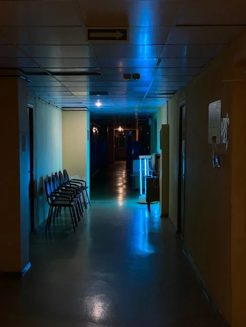
The sticker price for an online UVT probe in 2026 ranges from USD 4,000–12,000, depending on path-length options, housing material, and the inclusion of an automatic wiper; installation typically adds USD 1,500–3,000. Energy savings drive the payback. A 500-lamp UV bank running 8,000 h/yr at 0.40 kW per lamp, with electricity at USD 0.10/kWh and a 25% reduction from dose pacing, returns roughly USD 40,000/yr at a single mid-size plant (per HydropureWater field data, 2026). Chlorine savings run 15–30% because dose-paced UV allows operators to reduce over-chlorination safety margins.
Payback typically lands between 6 and 14 months on energy alone, well under the typical 5-year probe service life. Compliance upside is significant, as continuous UVT, intensity, and flow logs satisfy EPA, EU, and most state agency validation reporting — see the real-time water quality monitoring system buyer's guide for how this fits into a broader instrumentation strategy. The sensor functions as a self-funding instrumentation upgrade.
Selection Checklist Before You Buy
- Match path length to your expected UVT range: 1 mm for <30% UVT, 10 mm for 30–70%, 50 mm for >70% — wrong choice invalidates the measurement.
- Require automatic wiper or ultrasonic cleaning for any wastewater service; manual-only is a maintenance liability that erodes energy savings.
- Specify Modbus TCP or RTU output so the probe feeds existing SCADA, not a vendor-proprietary box.
- Demand NIST- or PTB-traceable calibration certificate and a minimum 2-year warranty.
- Confirm IP68 rating for submersible service and a 10 m maximum cable run without signal amplification.