Where Nanofiltration Sits on the Membrane Spectrum
A nanofiltration system is a pressure-driven membrane process between ultrafiltration (UF) and reverse osmosis (RO). The nanofiltration working principle rests on pore size 0.001–0.01 μm, MWCO 200–1,000 daltons, and feed pressure 50–300 psi (3.4–20.7 bar). NF removes most divalent ions and organics above about 200 Da while passing a large share of monovalent salts (Sutherland, Filtration+Separation, October 2008).
UF mainly strips suspended solids and macromolecules. RO removes essentially all dissolved ions. NF fills the selective middle band where hardness, color, and partial desalination are the real targets.
Engineers often call NF "loose RO" or "tight UF" because the skid layout matches those processes. Only the membrane cut-off changes. In a typical industrial train, NF follows pretreatment and UF. It either replaces RO when full desalination is unnecessary, or softens RO feed to cut scaling load. The practical split is simple. UF scrubs particles and microbes. NF strips hardness and organics in the 200–1,000 Da range. RO finishes the job when permeate conductivity must drop below 50 µS/cm.
Nanofiltration working principle and separation mechanisms
An NF membrane separates species through size exclusion, solution-diffusion, and Donnan exclusion at the same time. Size exclusion dominates for organics larger than the MWCO: those solutes are physically blocked, while smaller ones can pass. Solution-diffusion governs salt and small-molecule transport through the polyamide skin under the applied pressure gradient. Donnan exclusion arises because most commercial polyamide NF membranes carry a slight negative surface charge, which repels divalent anions more strongly than monovalent ions (per standard polyamide NF membrane specifications).
Labban et al. That framing matches field practice: divalent hardness and sulfate are rejected hard, while sodium and chloride often pass intentionally.
Mechanically, a nanofiltration system is a high-pressure pumping skid feeding spiral-wound elements. A typical element is a thin-film composite: a polyamide selective skin cast on a polysulfone support, rolled with feed and permeate spacers, and housed in a 2.5-inch, 4-inch, or 8-inch pressure vessel. Feed enters at 50–300 psi (3.4–20.7 bar). Permeate exits near atmospheric pressure. Concentrate is recycled or discharged. Single-pass industrial systems routinely achieve 85–95% recovery. Crossflow velocity is the main fouling lever: 0.1–0.3 m/s is the standard design window, high enough to scour the surface and low enough to keep pump energy in check. For higher-pressure desalination, paired industrial reverse osmosis systems are specified downstream of NF when full monovalent rejection is also required.
Key Parameters: Pore Size, MWCO, Pressure, and Rejection
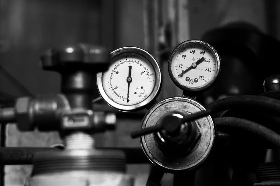
The numbers below are the design envelope a process engineer should carry into a P&ID meeting. They are drawn from manufacturer datasheets for spiral-wound polyamide NF elements and cross-checked against operating plants in the field (HydropureWater field data, 2026).
| Parameter | Typical NF Range | Notes for the design engineer |
|---|---|---|
| Pore size (nominal) | 0.001–0.01 μm (1–10 nm) | Defines the size-exclusion cutoff; not a measured physical pore but an equivalent |
| Molecular weight cut-off (MWCO) | 200–1,000 Da | 90% rejection of a reference solute (often sucrose or polyethylene glycol) at this molecular weight |
| Operating pressure | 50–300 psi (3.4–20.7 bar) | Versus 150–1,000 psi for brackish RO — the headline energy advantage |
| Divalent ion rejection (Ca²⁺, Mg²⁺, SO₄²⁻) | 95–99% | The workhorse spec for softening and sulfate removal |
| Multivalent organic rejection (dyes, humics, lactose) | 95–99% | Effective for color, COD, and recovery of high-value organics |
| Monovalent ion rejection (Na⁺, Cl⁻) | 20–80% | Variable with feed concentration; intentional pass-through is the NF feature, not a failure |
| Permeate flux (standard conditions) | 10–50 LMH | Declines with viscosity, scaling, and fouling; clean-water flux is the upper bound |
| Single-pass recovery | 85–95% | Pushing beyond 95% risks calcium sulfate and silica scaling |
| Temperature tolerance | 5–45 °C | Polyamide skin softens above 45 °C and loses rejection |
| pH tolerance (continuous operation) | 2–11 | Cleaning cycles can run 1–13 for short durations |
| Free chlorine tolerance | <0.1 mg/L continuous | Polyamide degrades rapidly above 1 mg/L; activated carbon or sodium bisulfite dosing is mandatory |
Three numbers from the table deserve emphasis because they are the ones equipment vendors most often misstate. First, the monovalent rejection band of 20–80% is wide because it scales with feed concentration and the specific membrane model—specify to the vendor's test data, not a generic catalogue claim. Second, the energy advantage over RO is real but bounded: NF typically cuts pump energy 30–60% relative to brackish RO on equivalent feed (per industry operating data, 2025). Third, the 85–95% recovery ceiling is set by concentration polarization and the solubility limits of calcium carbonate, calcium sulfate, and silica—not by membrane strength.
J. Environ. Health. Sci. Eng., 2008). Those results sit inside the monovalent and organic bands above. Specialized low-pressure layer-by-layer NF membranes have demonstrated above 95% rejection of MgCl₂, MgSO₄, and Na₂SO₄ at 2 bar with permeability above 10 LMH/bar (Liu et al., Journal of Membrane Science, 2015; EPA HERO 2956696). Most plants we size for softening still run conventional spiral polyamide elements nearer 100–200 psi, not the 2 bar research envelope.
Nanofiltration vs Ultrafiltration vs Reverse Osmosis
The matrix below is the comparison a process engineer should tape to the wall before a water-treatment scope review. It compiles the three membrane processes on the same axes so the choice becomes a one-glance decision rather than a multi-vendor guess.
| Parameter | Ultrafiltration (UF) | Nanofiltration (NF) | Reverse Osmosis (RO) |
|---|---|---|---|
| Pore size | 0.01–0.1 μm | 0.001–0.01 μm | <0.001 nm (non-porous) |
| MWCO | 1,000–500,000 Da | 200–1,000 Da | <200 Da |
| Operating pressure | 5–50 psi | 50–300 psi | 150–1,200 psi (brackish to seawater) |
| Salt rejection (NaCl) | 0% | 20–80% | 95–99.8% |
| Hardness (Ca²⁺, Mg²⁺) rejection | 0% | 95–99% | 99%+ |
| Organics rejection | Partial (high MW only) | 95–99% above 300 Da | 99%+ across the range |
| Microbe / virus removal | Log 3–6 | Log 4–6 | Log 6+ |
| Energy use (kWh/m³) | 0.05–0.3 | 0.3–0.8 | 0.8–4.0 |
| Target duty | TSS, turbidity, bacteria, oil emulsions | Hardness, color, partial desalination, dye/salt split | Total desalination, trace contaminants, ultrapure water |
The decision rule is straightforward. Specify UF when the job is removing suspended solids, oil, and microbes. Specify NF when hardness, color, and organics above 300 Da are the targets and full desalination is unnecessary. Specify RO when the permeate must be demineralized or the discharge limit is below 500 µS/cm. A second rule: NF is the cost-effective choice when monovalent salts can be left in the water. Where total desalination is required, NF often polishes ahead of RO. NF softens and decolors the feed so downstream MBR effluent reaching RO has a lower scaling index. That change lets the RO stage run at 75–85% recovery instead of 60–70%. Readers comparing biological membrane packages can review the mbr working principle before locking the NF–RO interface.
Industrial Applications of Nanofiltration Systems
NF earns its place in a water train whenever the rejection target is "selective" rather than "total." Five industrial duties cover most of the installed base.
Water softening. NF replaces lime-soda softening and weak-acid ion exchange for Ca²⁺/Mg²⁺ removal in boiler makeup and cooling-tower feed. The 95–99% divalent rejection eliminates brine regeneration and sludge disposal, and the 85–95% recovery keeps concentrate volume manageable. For feed hardness above 1,000 mg/L as CaCO₃, upstream NF still beats ion exchange on waste-stream footprint and OPEX consistency (HydropureWater field data, 2026). Compact point-of-use polishing for offices and factories often ends in a Commercial Direct Drinking Water System after NF softening of hard municipal feed.
Textile and dye processing. Reactive dyes in textile effluent typically have molecular weights of 600–1,500 Da, sitting squarely inside the NF rejection band, while the sodium chloride and sodium sulfate used in the dye bath pass through. This split enables dye/salt separation, color removal to <5 Pt-Co units, and water reuse back into the dyeing process. NF concentrate can be further processed for dye recovery. The operating envelope is documented in photovoltaic wastewater recycling case studies and similar high-salinity textile reuse trains, and is paired with dye wastewater treatment trains where residual color and COD require polishing.
Dairy and food processing. NF concentrates whey proteins, lactose, and peptides while letting water, monovalent salts, and minerals pass—the basis of whey demineralization and lactose recovery in dairy plants. Typical operating pressure 200–400 psi and 80–90% volume reduction concentrate the protein stream by 3–4×, after which evaporation or spray drying finishes the job. Lactose retention above 98% and chloride passage above 90% are the standard design targets.
Pharmaceutical and biotech process water. NF removes multivalent organics, endotoxins, and pyrogens from process water and buffer feeds without stripping monovalent buffer salts, which would otherwise have to be re-dosed downstream. Endotoxin reduction of log 3–5 is achievable on 300–1,000 Da cut-off membranes.
Landfill leachate and industrial reuse. NF polishes MBR or UF effluent to meet COD <100 mg/L and color <5 Pt-Co for discharge or reuse. A documented hybrid configuration is the Short SAT-NF treatment, which combines soil aquifer treatment with NF to upgrade effluent quality from municipal and industrial leachate sites (ResearchGate, Apr 2006). A second common pattern pairs NF with RO for landfill leachate ZLD, where NF handles the bulk of COD and multivalent salts, leaving RO to finish the trace contaminants.
Scale matters when sizing equipment. A residential NF element delivers 50–200 GPD (per standard consumer product data). An industrial NF plant with 8-inch spiral elements in multi-stage arrays runs 1,000–50,000 m³/day. Membrane chemistry is the same; capacity differs by three orders of magnitude. Plants that still settle high TSS before membrane stages often ask how a lamella clarifier working principle compares with dissolved-air flotation for that first cut.
Complementary Process Steps Beside Nanofiltration
Nanofiltration rarely stands alone in a full plant flowsheet. Oxidants, evaporators, and disinfectant generators often sit upstream or downstream of the membrane skid. The three questions below cover the unit operations buyers most often confuse with membrane separation itself.
What is the ozone generator working principle?
An ozone generator for water treatment creates O₃ by corona discharge or UV photolysis of oxygen, then dissolves that gas into the water to oxidize organics and inactivate microbes. Ozone breaks double bonds and aromatic rings that would otherwise foul NF membranes, so many color-removal trains dose ozone before or after the NF stage. Residual ozone must be quenched before polyamide NF, because free oxidant above about 0.1 mg/L as chlorine-equivalent damages the selective skin.
What is the MVR evaporator working principle?
An MVR evaporator compresses secondary vapor with a mechanical blower or fan and reuses that hot vapor as the heating medium for the same boiling chamber. The cycle cuts external steam demand on NF or RO concentrate that must reach near-zero liquid discharge. Most plants we size for NF–RO–evaporator trains run MVR when concentrate flow exceeds a few cubic meters per hour and electricity is cheaper than live steam.
What is the ClO2 generator working principle?
A chlorine dioxide generator produces ClO₂ on site, typically by reacting sodium chlorite with acid or chlorine under controlled stoichiometry. ClO₂ disinfects and oxidizes iron, manganese, and some taste-and-odor compounds without forming the same THM load as free chlorine. When ClO₂ is used ahead of NF, residual oxidant still requires carbon or bisulfite destruction so the polyamide membrane sees free chlorine below 0.1 mg/L continuous.
Choosing an NF System: Pretreatment, Recovery, and Operating Costs
Three design decisions determine whether an NF plant runs cleanly for five years or scales up in month six: pretreatment, recovery setpoint, and CIP frequency.
Pretreatment is non-negotiable. NF feed should meet silt density index <5, turbidity <1 NTU, and free chlorine <0.1 mg/L. A standard train is multimedia filtration followed by activated carbon (or sodium bisulfite dosing) and a 5 µm cartridge guard, protected upstream by multi-media pretreatment filters sized to the feed flow. Skipping the multimedia filter is the most common cause of premature NF fouling in industrial installations.
Recovery is the main operating lever. Single-pass NF typically runs 85–95% recovery; pushing past 95% raises concentrate osmotic pressure, accelerates flux decline, and risks calcium carbonate, calcium sulfate, or silica scaling on the membrane surface. The recovery ceiling should be set by a scaling projection against the actual feed chemistry, not a vendor default.
Operating cost is driven by three line items. Pump energy: 0.3–0.8 kWh/m³ for NF versus 0.8–4.0 kWh/m³ for RO, an order-of-magnitude difference at the upper end. Membrane replacement: every 3–5 years under normal operation, with element cost typically 20–35% of lifetime OPEX. CIP chemicals: every 1–4 weeks depending on feed water, using pH 1–2 acid and pH 12–13 caustic circulations. A properly specified NF system typically pays back versus RO in 1–3 years on softening-only and decolorization duty. Lower transmembrane pressure and higher flux cut energy and membrane-replacement cost (per HydropureWater system economics, 2026). For sites where scaling or biological fouling is chronic, pair the NF skid with an automatic chemical dosing system to stabilize recovery and extend CIP intervals.
Selection checklist before you issue an RFQ:
- Confirm the duty is selective (hardness, color, dye/salt split) rather than total desalination.
- Require SDI <5, turbidity <1 NTU, and free chlorine <0.1 mg/L at the NF feed flange.
- Set recovery from a scaling projection on actual CaCO₃, CaSO₄, and silica, not a catalogue default.
- Specify divalent and monovalent rejection to the vendor's test protocol at your feed TDS.
- Budget CIP every 1–4 weeks and membrane replacement every 3–5 years in the OPEX model.
- Decide whether RO polishing is required when permeate must stay below 500 µS/cm.
- Map concentrate disposal or MVR/ZLD cost before locking array recovery above 90%.
Who this is for. Plant engineers and EPC teams sizing softening, decolorization, dairy fractionation, or leachate polishing trains where monovalent salts can remain in the permeate.
Who should look elsewhere. Specifiers who need full demineralization, seawater desalination, or permeate conductivity well below 50 µS/cm should start with RO, not NF alone.
Next step. If your feed analysis and recovery target are ready for a skid review, send the water report through our request-quote form and we will return a duty-matched NF or NF–RO scheme.
Frequently Asked Questions
What is a nanofiltration system and how does it differ from RO?
A nanofiltration system is a pressure-driven membrane process with 200–1,000 Da MWCO that removes divalent ions and larger organics while passing many monovalent salts. Versus reverse osmosis, NF runs at 50–300 psi instead of 150–1,200 psi, rejects 20–80% of monovalent salts versus 95–99.8%, and uses 30–60% less pump energy. Choose NF for softening and decolorization; choose industrial reverse osmosis systems when total desalination is required.
What pore size and MWCO define an NF membrane?
NF membranes are specified by an equivalent pore size of 0.001–0.01 μm (1–10 nm) and a molecular weight cut-off of 200–1,000 daltons. Solutes lighter than about 200 Da pass through; solutes heavier than about 1,000 Da are rejected at 95–99%. The in-between range is partial rejection and depends on the membrane model, feed concentration, and operating pressure.
What operating pressure does a nanofiltration system need?
Standard industrial NF runs at 50–300 psi (3.4–20.7 bar), with 100–200 psi covering most softening and decolorization duty. Higher pressure is required when the feed TDS is elevated or the recovery target is above 90%. Research LBL membranes have shown useful divalent rejection at about 2 bar, but most commercial spiral plants still sit in the classic pressure band.
Can NF replace ion exchange for water softening?
Yes, for feed hardness up to about 1,000–1,500 mg/L as CaCO₃, NF with 95–99% divalent rejection can replace sodium-cycle ion exchange without the brine-regeneration waste stream. Above that range, NF and ion exchange are sometimes run in series, with NF handling the bulk removal and ion exchange polishing the residual hardness.
What feed-water limits apply before NF?
NF feed should meet SDI <5, turbidity <1 NTU, free chlorine <0.1 mg/L, temperature 5–45 °C, and pH 2–11 continuous. Pretreatment is typically multimedia filtration followed by activated carbon or bisulfite dosing and a 5 µm cartridge guard; multi-media pretreatment filters are the most common first stage.