Why Installation and Commissioning Are Treated as a Single Discipline for ED Systems
Installation and commissioning of an electrodialysis (ED) system are governed as one continuous scope by AWWA B116-19, the American Water Works Association standard titled "Electrodialysis and Ion-Exchange Membrane Systems," effective August 1, 2019 (the first edition was approved January 24, 2015). The standard's own scope statement covers "the design, procurement, installation, and commissioning of IEM systems" as a single thread, not four separate work packages. For any 2026 project this 2019 edition remains the active reference, and any earlier copies should be retired from the spec library.
The standard also states explicitly that it is "not a specification" and "does not contain all of the engineering and administrative information normally contained in specifications." That disclaimer is the gap this field guide fills: AWWA gives you the framework, but the contractor is expected to write the project-specific commissioning procedure. Treating the two disciplines as one package also protects the contract — most EPC agreements retain 5–10% of skid value until signed performance acceptance, so installation quality that is only verified during commissioning becomes a direct liability.
Pre-Arrival Planning: Documents, Pretreatment, and Site Readiness
Sixty to eighty percent of ED start-up failures originate upstream of the skid itself — in suspended solids carryover, hardness breakthrough, or organic fouling from the feed. Pre-arrival planning exists to surface those problems two weeks before the truck arrives, not two days after. Treat the items below as hold-points: commissioning cannot begin until each line is signed off.
| Category | Item | Specification / Threshold |
|---|---|---|
| Documents on site | P&ID, electrical single-line, IO list, MSDS for membrane storage solution, OEM CIP chemical list | All revisions current; storage MSDS typically sodium bisulfite 0.1–1.0% |
| Feed water — turbidity | NTU at skid inlet | <1 NTU (HydropureWater field data, 2026) |
| Feed water — free chlorine | mg/L | <0.1 mg/L; chlorination must be followed by dechlorination (per AWWA B116-19) |
| Feed water — hardness | mg/L as CaCO₃ | <40 mg/L, or upstream softener confirmed operational |
| Feed water — Fe / Mn | mg/L | <0.05 mg/L each |
| Civil — floor load | Operating weight, 200 m³/day skid | 800–1,200 kg; verify pad rating before crane lift |
| Civil — clearances | Service access | ≥1 m on all service sides for stack withdrawal |
| Electrical — supply | 3-phase, voltage tolerance | ±10% of OEM nameplate |
| Electrical — grounding | Resistance to earth | <5 Ω |
The civil readiness check is the most commonly skipped item. A 200 m³/day skid rarely exceeds 1,200 kg operating weight, but a thickened concentrate loop with full piping can push a second-floor housekeeping pad beyond its design load — and the failure mode is concrete cracking, not a soft alarm. Electrical readiness needs the same discipline: a dedicated breaker, a grounding electrode under 5 Ω, and a UPS-backed instrumentation loop so a plant-side power dip does not corrupt the first 24 hours of trend data.
Mechanical Installation: Skid Placement, Piping, and Stack Receiving
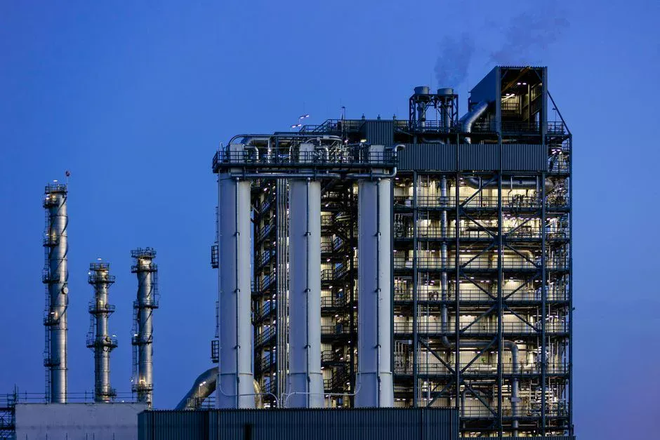
Mechanical installation follows a fixed physical sequence: crane lift onto the housekeeping pad, anchor-bolt torque to the OEM drawing (M16 anchors typically take 90–110 Nm), then laser alignment of interconnecting piping before any flange is bolted up. Skewed piping loads the stack end-plates asymmetrically and is the most common cause of gasket weeping at first pressurization — a problem that is mechanical, not chemical, and will not be fixed by re-torquing the stack.
Stack receiving deserves its own protocol. Never lay a hydrated stack on its side; the membrane packet will shift under gravity and the cell spacers will compress unevenly. Never expose dry membranes to air for more than 30 minutes without re-wetting with the storage solution; irreversible shrinkage begins past that window and the affected cell pair will fail to seal on first compression. Process lines should be flushed with deionized or RO permeate water for 5–10 turnovers before connecting to the stack — weld scale, lubricating oil, and PTFE tape debris entering an unflushed stack will score the spacer screens and seed the first CIP. Field-side multi-media pretreatment filtration installed ahead of the skid reduces this loading significantly. Each instrument — conductivity probe, flow switch, pressure transmitter, pH sensor — must arrive with a calibration certificate still inside its validity window, otherwise the performance test numbers are not defensible to the client's QA/QC team.
Hydraulic Commissioning: Flushing, Leak Testing, and Stack Hydration
Hydraulic commissioning is the highest-risk phase because every error here survives into commercial operation. The numbers below are the values an engineer should write into the commissioning plan, not ranges to negotiate at site.
| Step | Parameter | Value | Hold / Duration |
|---|---|---|---|
| Piping flush | Turnovers on deionized or RO permeate | 5–10 turnovers per loop | Until drain conductivity stabilizes |
| Hydrostatic leak test — diluate loop | Test pressure | 1.25× design, typically 0.25–0.3 MPa | 30 min; pressure drop >2% = fail |
| Hydrostatic leak test — concentrate loop | Test pressure | 1.25× design, typically 0.25–0.3 MPa | 30 min; pressure drop >2% = fail |
| Stack hydration | Circulation time on storage solution or permeate | 2–4 hours | Full wetting of AEM/CEM |
| Post-hydration flush | Feed water flush to drain | 30 minutes | Before energization |
| Flow verification | Per loop vs. design | ±10% | Pre-energization gate |
| Air bleed | All high points | Visual + conductivity stabilization | Pre-energization gate |
Leak testing is run on the diluate and concentrate loops separately — never on a common manifold — so a pressure-drop failure can be traced to one circuit. A drop greater than 2% over the 30-minute hold points to a gasket, fitting, or membrane seal failure; do not attempt to compensate by re-torquing the stack end-plates, since over-torque causes the compression-set failure mode described later in this article. After leak test, the stack hydration step is non-negotiable: circulating storage solution or permeate for 2–4 hours drives water into both anion and cation exchange membranes, which arrive from the factory only partially hydrated. Trapped air is the silent killer here — pockets in the manifold create localized current density spikes during energization, and the resulting hot spots can blister an anion membrane within minutes.
Electrical and Controls Commissioning: Graded Voltage Ramp-Up
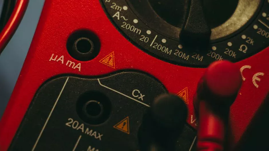
Before any voltage is applied, phase rotation must be verified against the OEM drawing. A polarity reversal on a stack that is not designed for EDR (electrodialysis reversal) operation causes irreversible anion-membrane blistering — the membrane swells, delaminates from its reinforcement, and the affected cell pair must be replaced. The protection is a single phase-rotation test, but the failure is a stack rebuild.
The graded voltage ramp is the standard sequence: start at 0.1 V per cell pair, hold for 15–20 minutes while monitoring current and stack temperature, then step up to the next setpoint. Typical design voltage is 0.5–2.0 V per cell pair depending on feed salinity and target recovery. Current should rise roughly linearly with voltage during the ramp; a flat current response indicates an air pocket or a dry membrane, and the ramp must be paused until the cause is identified. The full alarm and interlock set — high-voltage, high-pressure, low-flow, and conductivity-out-of-range trips — is proven by simulation (forced setpoint, not just observation) so the trip is known to fire before a real process upset tests it. The PLC-to-DCS handshake follows the project IO list, mirroring the approach used in a typical SCADA integration for wastewater plants, with every tag (flow, conductivity, pressure, voltage, current) verified for both direction and engineering units.
Performance Acceptance Test: What 'Done' Looks Like
The performance acceptance test is the contractual hand-off trigger. AWWA B116-19 §6.4 references a continuous 72-hour run on design feed water at design flow as the industry-standard duration — anything shorter is not defensible to the client's QA/QC team. The system must be operating in automatic, not manual, for the full 72 hours so the controls logic (not the operator) is what is being accepted.
Three pass criteria cover the contractual position: (1) target conductivity reduction achieved, typically 50–95% per pass depending on application; (2) current efficiency above 85% at design voltage, calculated as the ratio of salt removed to charge passed; (3) diluate and concentrate loop pressure drops within ±10% of the OEM performance curve. Data is logged at 15-minute intervals: feed, diluate, and concentrate conductivity, pH, flow, voltage, and current. From those values, specific energy consumption (kWh/m³) is calculated and compared to the OEM guarantee — typically 0.5–2.5 kWh/m³ for brackish ED. The hand-off package then assembles four documents the client will demand before releasing retention: as-built drawings, calibrated instrument certificates, an operator training log, and a signed punch list. Where the upstream train is governed by an industrial RO system or the chemistry by an automatic chemical dosing skid, the corresponding commissioning records should be cross-referenced so the client sees one integrated package.
Common Commissioning Failures and How to Prevent Them
Most ED commissioning failures are repeatable, and most are preventable with a single check at the right point in the sequence. The table below is built from field-service history; treat each row as a gate to clear, not a problem to troubleshoot after the fact.
| Failure Mode | Mechanism | Mitigation |
|---|---|---|
| Dry membrane exposure | Irreversible membrane shrinkage; cell pair fails to seal on first compression | Keep membranes wet; limit air exposure <30 min; re-wet with storage solution if exceeded |
| Gasket compression set | Over-torquing the stack end-plates; leak path develops after first heat cycle | Torque to OEM spec; re-torque only after first thermal cycle per OEM procedure |
| Hardness scaling on concentrate side | Rising stack resistance; current drop at constant voltage | Verify softener regeneration before energization; confirm scale-inhibitor dosing is active |
| Polarity reversal on non-EDR stack | Anion-membrane blistering and delamination | Phase-rotation check before first energization; lock the breaker orientation |
| Air pocket in manifold | Localized current density spike; membrane hot spot on energization | Bleed all high points; confirm flow > design minimum before applying voltage |
The pattern across these failures is consistent: each is cheap to prevent and expensive to repair. A stack that blisters on day one is a six-figure rebuild and a multi-week delay; a 10-minute phase-rotation check on day zero is the entire mitigation. For a parallel view on a related separation technology, the filter press commissioning guide follows the same gate-and-proof structure. Alarm rationalization during the controls phase is covered in detail in this alarm management for wastewater SCADA reference.
Frequently Asked Questions
How long does commissioning an electrodialysis system take?Typical commissioning duration is 5–10 working days for systems up to 200 m³/day, excluding pretreatment integration and any upstream retrofit work.
What pressure is used for an ED stack leak test?Pressurize the diluate and concentrate loops separately to 1.25× design pressure, typically 0.25–0.3 MPa, and hold for 30 minutes; a pressure drop greater than 2% indicates a leak.
What is the standard voltage ramp for ED stack energization?Start at 0.1 V per cell pair and step up every 15–20 minutes to the design value of 0.5–2.0 V per cell pair, monitoring current at each step.
Which AWWA standard governs ED system commissioning?AWWA B116-19, "Electrodialysis and Ion-Exchange Membrane Systems," effective August 1, 2019, covers design, procurement, installation, and commissioning as a single scope.