What Makes Bakery Wastewater a DAF Design Problem
Bakery influent from mixer, kettle, and floor washdown delivers TSS of 1,200 mg/L, FOG of 1,200 mg/L, COD of 4,400 mg/L, and BOD of 3,300 mg/L at pH 6–9 in a typical cookie and cracker plant (FRC Systems 2026 case study). Daily flows stay modest — the FRC facility runs 36,000 GPD (≈136 m³/d) — but peak-to-average ratios reach 2.5–3× during clean-in-place (CIP) cycles and product changeovers, so an equalization tank sized at 8–12 hours of average flow is a prerequisite to any food processing wastewater treatment engineering guide benchmark. The FOG fraction in bakery effluent is emulsified rather than free: surfactant residues from chlorinated alkaline and acidic sanitizers used on kettles and conveyor lines create stable 1–10 µm oil-in-water droplets that resist gravity separation in an API or CPI separator yet respond well to microbubble attachment in dissolved air flotation. A DAF unit designed for municipal sewage at HSLR 5–10 m/h and A/S 0.005–0.015 will underperform on this stream by 30–50% on TSS and FOG removal if applied without resizing, because bakery solids are lower density (flour, dough residue, insoluble starch) and the oil droplets carry surface charges that suppress bubble-particle attachment unless chemistry is applied.
Core DAF Design Parameters for Bakery Streams
Four numbers govern a bakery DAF sizing: hydraulic surface loading rate (HSLR), air-to-solids (A/S) ratio, recycle ratio, and saturation pressure. HSLR is the volumetric flow per unit tank surface area, expressed in m/h, and it sets the tank footprint: Surface area = Q / HSLR. For high-FOG bakery streams the HSLR window is 10–20 m/h, versus 5–10 m/h for municipal primary clarification (per Hixson 2026 design criteria); pushing above 20 m/h on bakery effluent typically drops TSS removal below 80% because bubble residence time falls under 3 minutes. The A/S ratio expresses mass of dissolved air released per mass of TSS in the feed; bakery influent at 800–1,500 mg/L TSS requires A/S of 0.02–0.06 kg air per kg TSS, roughly 3–4× the municipal target. Recycle ratio — the fraction of clarified effluent pressurized and saturated with air then re-mixed with the influent — runs 10–30% for bakery service; 20% is a defensible default that gives a bubble density near 1.5 × 10⁶ bubbles/L without spiking pump horsepower. Saturation pressure of 4–6 bar is standard; above 6 bar the marginal gain in dissolved air concentration falls under 8% per bar while compressor energy rises 40–60% because saturation power scales with pressure. Microbubble diameter of 10–100 µm governs attachment kinetics, with the 30–50 µm band optimal for FOG capture — smaller bubbles rise too slowly to clear the tank, larger ones burst at the surface and re-disperse the oil. Dissolved air concentration in the whitewater follows Henry's law: at 5 bar saturation and 20°C the recycle stream holds ~70 mg/L of dissolved air (Hixson 2026), which is the source term for the A/S calculation. The table below summarizes the parameter set a bakery engineer should hand to procurement.
| Parameter | Bakery DAF Range | Municipal DAF Range | Design Implication |
|---|---|---|---|
| HSLR (m/h) | 10–20 | 5–10 | Sets tank surface area |
| A/S ratio (kg air / kg TSS) | 0.02–0.06 | 0.005–0.015 | Sets saturator and recycle pump size |
| Recycle ratio (%) | 10–30 | 5–15 | Sets recycle pump and saturator volume |
| Saturation pressure (bar) | 4–6 | 4–5 | Drives compressor power |
| Microbubble diameter (µm) | 30–50 optimal | 10–100 | Drives nozzle and needle valve spec |
| Hydraulic residence time (min) | 5–10 | 10–20 | Sets effective tank depth |
For a 136 m³/d bakery stream at 15 m/h HSLR, the required flotation surface area is 136 ÷ 24 ÷ 15 = 0.38 m² per m³/d, or roughly 52 m² total — a tank footprint easily handled by a HydropureWater dissolved air flotation system in the 50 m³/h class with an integrated saturator and recycle loop.
Dual-Stage DAF: How the Two-Stage Configuration Works on Bakery Effluent
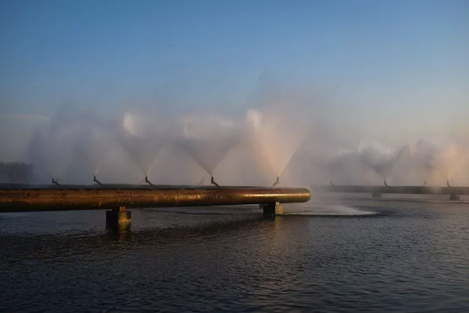
For bakery influent above 4,000 mg/L COD — the FRC plant runs 4,400 mg/L — a single polymer-aided DAF leaves residual FOG of 150–250 mg/L and struggles to hit discharge limits below 100 mg/L without a downstream biological step. A dual-stage DAF configuration solves this by splitting removal across two sequential units with different chemistry. Stage 1 runs chemical-free: raw effluent enters a flocculation tank with no coagulant, then flows into the first DAF where microbubbles attach to heavier organic particulates — flour fines, dough residue, insoluble starch granules — by physical entrainment. Typical Stage 1 removal is 50–65% TSS and 30–45% FOG without polymer, and the floated sludge is unusually thick at 4–8% dry solids because the captured material is fibrous and drains rapidly. Stage 2 treats the Stage 1 clarifier overflow with a coagulant dose of PAC or alum at 50–150 mg/L plus an anionic polymer at 0.5–3 mg/L, adjusted through an automatic chemical dosing system for coagulant and polymer feed. The chemistry destabilizes the emulsified FOG and colloidal organics that survived Stage 1, forming 200–500 µm flocs that the second DAF unit captures on the next pass. Combined removal across both stages exceeds 90% TSS and 90% FOG, with effluent typically under 100 mg/L FOG and 150 mg/L TSS — clean enough to feed an SBR, MBBR, or MBR for biological polishing. Splitting chemistry across two stages avoids overdosing Stage 1 (where particulates already float) and cuts total polymer consumption 20–40% compared to single-stage chemical DAF, because the dose is targeted at the contaminant class actually present in each stream. Stage 2 sludge is thinner at 3–5% DS and gelatinous, so the two sludge lines should run to separate dewatering stations — or at minimum to a single plate and frame filter press for DAF sludge dewatering with separate feed pumps and conditioning tanks. A dual-stage setup at the FRC influent profile fits a HydropureWater DAF-50 (50 m³/h) per stage, with both units sharing a common saturator to cut CAPEX.
Single-Stage vs Dual-Stage DAF: When Each Configuration Wins
The configuration decision is driven by three variables: influent COD, FOG concentration, and the discharge limit on the treated stream. A single-stage polymer-aided DAF handles influent COD below 3,000 mg/L and FOG below 800 mg/L with 80–90% TSS and FOG removal in one pass — adequate for bakeries that send DAF effluent to a municipal sewer with sufficient biological capacity. Dual-stage DAF is justified when influent COD exceeds 4,000 mg/L, FOG exceeds 1,000 mg/L, or the plant must meet a discharge limit below 100 mg/L COD without a biological step (FRC Systems 2026). The footprint penalty is real: dual-stage requires 1.6–1.9× the floor area of a single-stage unit at the same flow, which can be mitigated by selecting a high-HSLR (>18 m/h) DAF for Stage 1 and accepting lower Stage 1 removal (45–55% TSS) in exchange for the smaller tank. CAPEX for the DAF equipment alone runs 40–70% higher for dual-stage, but total system CAPEX including equalization, chemical dosing, and sludge handling is only 15–25% higher because the supporting infrastructure is shared. Sludge volume from a dual-stage system is typically 15–25% lower than single-stage at matched removal efficiency because each chemistry dose is targeted to a narrower contaminant class. For the FRC 36,000 GPD (≈136 m³/d) bakery case at the published influent profile, a dual-stage DAF with two HydropureWater DAF-50 units (50 m³/h each) fits inside a 60 m² equipment room including the saturator skid and chemical dosing cabinets. The decision matrix below makes the configuration choice auditable.
| Selection Criterion | Single-Stage DAF | Dual-Stage DAF |
|---|---|---|
| Influent COD | < 3,000 mg/L | > 4,000 mg/L |
| Influent FOG | < 800 mg/L | > 1,000 mg/L |
| TSS removal | 80–90% | > 90% |
| FOG removal | 80–90% | > 90% |
| Polymer consumption | Baseline | 20–40% lower than single-stage chemical DAF |
| Footprint (relative) | 1.0× | 1.6–1.9× |
| Equipment CAPEX (relative) | 1.0× | 1.4–1.7× |
| Total system CAPEX (relative) | 1.0× | 1.15–1.25× |
| Sludge volume | Baseline | 15–25% lower at matched removal |
| Best-fit bakery profile | Cookie line, bread bakery, low-CIP plant | Cracker plant, biscuit line, high-FOG kettle washdown |
Pretreatment, Sludge Handling, and Where DAF Fits in the Bakery Treatment Train
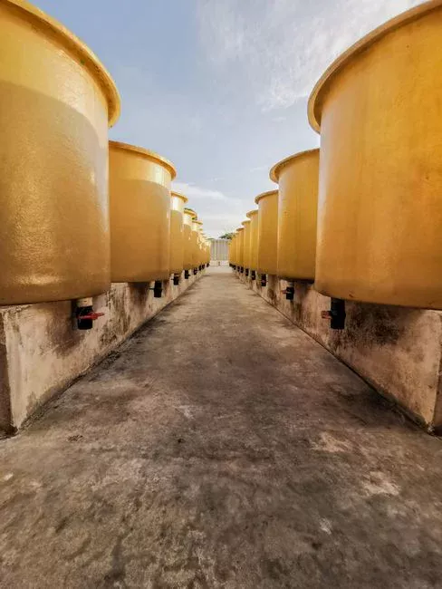
DAF does not stand alone — it sits in a treatment train with defined upstream and downstream interfaces. Upstream, a rotary bar screen upstream of the DAF with 3–5 mm aperture removes dough solids, packaging fragments, and CIP debris before they reach the DAF feed pump and saturator; missing this step is a leading cause of nozzle clogging and pump seal failure. pH adjustment to 6.5–7.5 immediately ahead of coagulant injection optimizes alum and PAC performance, so a pH probe linked to the dosing system is standard rather than optional. Downstream of DAF, the FOG-reduced effluent (typically <100 mg/L FOG, <150 mg/L TSS) flows to biological treatment — SBR, MBBR, or MBR depending on discharge target and footprint — to reach <50 mg/L COD for surface discharge or sewer limits below 200 mg/L COD. Sludge from the DAF stages at 3–6% DS routes to a plate and frame filter press for DAF sludge dewatering sized for the cake dryness target (20–35% DS); bakery DAF sludge is high in organics and grease, making it suitable for anaerobic co-digestion with other food-processing waste or for rendering where permitted. The equalization tank upstream of DAF should hold 8–12 hours of average flow to dampen the 2.5–3× peak-to-average swings from CIP and product changeovers — sizing below 6 hours will push the saturator and recycle pump outside their rated turndown and cause whitewater pressure instability. For plants that also run beverage lines, the beverage wastewater treatment process guide for 2026 covers the shared equalization and screening design with bakery effluent.
Frequently Asked Questions
What HSLR should I use for a bakery DAF with 1,200 mg/L FOG?
10–20 m/h, with 15 m/h as the design baseline for high-FOG bakery streams; pushing above 20 m/h drops FOG removal below 80% because hydraulic residence time falls under 3 minutes (Hixson 2026). For a 136 m³/d stream at 15 m/h HSLR, required flotation surface area is approximately 52 m².
What air-to-solids ratio removes emulsified bakery FOG?
0.02–0.06 kg air per kg TSS for bakery influent at 800–1,500 mg/L TSS, achieved with 4–6 bar saturation pressure and 20% recycle at 20°C (per Henry's law, ~70 mg/L dissolved air in the whitewater). Lower A/S ratios leave residual FOG above 150 mg/L.
When does a dual-stage DAF beat a single-stage DAF?
When influent COD exceeds 4,000 mg/L or FOG exceeds 1,000 mg/L — the FRC 2026 case (COD 4,400 mg/L, FOG 1,200 mg/L) used dual-stage to hit >90% removal; single-stage would have left 150–250 mg/L residual FOG. The trade-off is 1.6–1.9× the footprint and 15–25% higher total system CAPEX.
What polymer dose is typical for bakery DAF Stage 2?
0.5–3 mg/L anionic polymer plus 50–150 mg/L PAC or alum, metered through an automatic chemical dosing system for coagulant and polymer feed; Stage 1 is chemical-free. Splitting chemistry across two stages cuts total polymer consumption 20–40% versus a single-stage chemical DAF.
Can the DAF system be used in both stages of a dual-stage bakery plant?
Yes — the HydropureWater dissolved air flotation system is factory-tested on food-processing influents and ships in capacities from 4–300 m³/h, covering Stage 1 high-HSLR service, Stage 2 polish duty, and shared saturator skids for both units.
How do I monitor residual FOG leaving the DAF to stay ahead of permit excursions?
Install an on-line FOG analyzer downstream of Stage 2 with a 4–20 mA signal back to the SCADA; the oil and grease online monitoring system guide for 2026 covers sensor selection and sampling loop design for emulsified bakery effluent.