Build a Tasikmalaya data center water balance before selecting equipment
A data center in Tasikmalaya needs separately engineered treatment for each wastewater stream, not one generic system. Continuous cooling-tower blowdown should first be characterized by conductivity, pH, suspended solids, hardness, silica, total dissolved solids and the cooling-water chemical program. If reuse as cooling makeup is feasible, pretreatment may use filtration and hollow-fiber ultrafiltration before reverse osmosis, but equipment must be selected from measured Tasikmalaya feed chemistry and concentrate-disposal routes. Domestic sewage, construction flushing and utility wastewater require their own treatment and sampling. Site-specific flows, discharge permits and receiving-WWTP limits must be confirmed before sizing; the supplied research provides no verified Tasikmalaya limits.
A defensible design starts with a measured data center water balance. Install separate metering for cooling makeup, cooling-tower blowdown, evaporation, process drainage, construction flushing and reuse flow. Where operating history is available, trend makeup and blowdown for at least 12 months to capture seasonal and operating changes, then compare metered blowdown with the theoretical value calculated from cycles of concentration.
Genesis Water Technologies, 2026 reports that actual blowdown commonly exceeds theoretical blowdown by 15–30% because of unmeasured losses and emergency dumps. That gap matters because a system sized only from evaporation and cycles of concentration may be undersized for the observed purge.
| Water-balance input | Evidence or information required | Decision supported |
|---|---|---|
| Cooling configuration | Evaporative or other configuration; operating hours; redundancy | Separates continuous and standby treatment requirements |
| Cycles of concentration | Normal operating range, controls and chemical program | Calculates theoretical blowdown and assess scaling risk |
| Makeup and blowdown | Separate metering and at least 12 months of seasonal trends where available | Establishes measured flow and uncertainty |
| Evaporation and drainage | Independent measurements where practical | Closes the site water balance |
| Reuse demand | Required flow, product-water specification and operating hours | Defines treatment objectives and redundancy |
| Discharge route | Sewer or receiving-WWTP route and acceptance criteria | Confirms whether reuse is necessary or discharge treatment is sufficient |
Preliminary sizing should use measured flows, feed chemistry and operating conditions rather than data-center MW alone, consistent with HydropureWater’s 2026 Malang engineering guide. The 2026 data center cooling blowdown treatment methodology provides a useful framework, but its geographic assumptions must not be transferred to Tasikmalaya. The cooling blowdown reuse and equipment selection framework can also support preliminary stream mapping.
Separate the wastewater streams before choosing treatment
Cooling-tower blowdown, construction flushing and non-process wastewater should remain separate because their flow patterns, contaminants and acceptable disposal routes differ. Combining them before characterization can overload a reuse system with intermittent construction chemicals or make the resulting blend unsuitable for the receiving sewer.
Cooling blowdown is the principal continuous operating stream. Its flow varies with cooling operation, evaporation and cycles of concentration, and it contains concentrated dissolved solids, suspended matter and residual treatment chemicals. It is not interchangeable with relatively stable domestic sewage.
Construction fill-and-flush water is intermittent. Cleaning agents, corrosion inhibitors and biological residues introduced during commissioning can change its chemistry, so commissioning samples must represent the actual discharge rather than operating blowdown. Domestic sewage, generator exhaust washwater, chiller drains and other utility wastewater also require independent assessment. The supplied research contains no Tasikmalaya-specific generation rates for these streams.
| Stream | Characterization required | Preliminary route decision |
|---|---|---|
| Cooling-tower blowdown | Flow, conductivity, pH, suspended solids, hardness, silica, TDS, alkalinity and residual chemicals | Reuse, discharge treatment or a permitted blend; selection follows chemistry and route confirmation |
| Construction flushing | Intermittent flow; cleaning agents, corrosion inhibitors and biological residues | Separate collection, sampling, treatment or disposal |
| Domestic sewage | Flow, organic load, nutrients, solids and discharge requirements | On-site biological treatment, sewer or receiving-WWTP route |
| Utility wastewater | Source-specific pollutants, including oil and grease where relevant | Source isolation followed by suitable physical or biological treatment |
For every stream, confirm whether it will be reused on site, discharged to a sewer or receiving WWTP, or managed through another approved route. The domestic sewage treatment and compliance reference illustrates the stream-specific approach, but it does not establish Tasikmalaya’s limits or regulatory route.
Characterize cooling blowdown and cooling makeup reuse potential
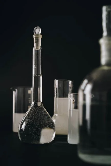
Cooling blowdown can become an internal cooling makeup water source only when its chemistry, operational variability and concentrate route support reliable reuse. Test conductivity, pH, suspended solids, hardness, silica, total dissolved solids, alkalinity and relevant residual treatment chemicals; include microbiological indicators where ultrafiltration or reuse is contemplated.
For an evaporative system, the theoretical relationship is:
blowdown ratio = 1 ÷ (cycles of concentration − 1)
Genesis Water Technologies, 2026 reports blowdown of 25% of makeup volume at 4 CoC and 20% at 6 CoC. The change from 4 to 6 CoC is therefore a 5-percentage-point reduction, or 20% of the original blowdown volume—not a 50% reduction. Higher concentration can increase scaling, corrosion and microbiological-control risks, so chemical capability and operating controls must be reviewed before the ratio is changed.
| Checkpoint | Engineering significance | Information needed before equipment selection |
|---|---|---|
| Measured versus theoretical blowdown | Quantifies losses and emergency discharges that alter treatment capacity | Separate flow metering and seasonal trend data |
| Cooling-water chemistry | Defines membrane and scaling conditions | Residual biocide, corrosion inhibitor, dispersant and scale-control information |
| Hardness, silica and TDS | Governs pretreatment and concentrate-management limits | Source-water and blowdown analyses across operating conditions |
| Microbiological quality | Protects RO systems and reuse applications | Indicator testing appropriate to the proposed reuse route |
| Recovery and product quality | Determines whether desalination is justified | Cooling makeup specification, recovery target and concentrate disposal route |
HydropureWater’s 2026 Malang guide notes that cooling-loop optimization can reduce the flow requiring treatment, but the saving must be calculated from the correct blowdown relationship and a metered baseline. The IDE Tech, 2026 example of approximately 95% recovery with permeate silica of about 1 mg/L is an industrial reference point, not a guaranteed Tasikmalaya target.
Before purchasing a large reuse train, repair leaks, eliminate once-through cooling, optimize controls and improve self-cleaning filtration. These steps can reduce both the required treatment flow and the contaminant load entering the proposed train. The 2026 data center cooling blowdown treatment methodology can then be used to compare measured reuse scenarios.
Compare filtration, ultrafiltration and reverse osmosis for each reuse route
The appropriate treatment train follows the intended reuse specification. Media or multi-media filtration is the starting point where suspended solids and turbidity must be reduced before sensitive equipment. Hollow-fiber ultrafiltration is suitable where bacteria, colloids and suspended solids must be removed before reverse osmosis or another polishing step.
The hollow-fiber ultrafiltration pretreatment for cooling blowdown uses 0.03-micron PVDF membranes, accepts turbidity up to 300 ppm, includes automatic backwash and air scour, and is available from 2,000 to 40,000 L/h. Those specifications identify an available configuration; they do not establish that it is correctly sized for Tasikmalaya.
| Treatment option | Primary function | Best-fit decision condition | Key issue to verify |
|---|---|---|---|
| Multi-media filtration | Suspended-solids and turbidity reduction | Feed requires solids removal before sensitive equipment | Backwash waste and upstream loading |
| Hollow-fiber UF | Bacteria, colloid and suspended-solids barrier | RO feed requires membrane protection | Feed turbidity, fouling and cleaning method |
| Industrial RO for cooling makeup reuse | Dissolved-solids reduction | Cooling makeup requires lower dissolved salts | Recovery, scaling and concentrate route |
| Physical treatment for lower-risk uses | Removal of selected suspended contaminants | Toilet flushing, washing or irrigation has a compatible specification | Whether the product stream satisfies each intended use |
Open Engineering Inc, 2026 found that UF plus RO increased energy use to more than five times the freshwater case, while improved cycles of concentration reduced blowdown and chemical consumption. This does not disqualify RO; it means that pretreatment, energy, recovery and cooling-system operation must be evaluated together. The RO capacity and sizing guide for industrial buyers provides a basis for checking flow and feed assumptions.
For higher recovery, the design must account for scale-forming silica, calcium carbonate and calcium sulfate. IDE Tech, 2026 states that conventional brackish-water RO commonly plateaus at 75–80% recovery before scaling and operational constraints increase. Define the concentrate route before selecting RO: without a feasible treatment or disposal route, high recovery is not an operational solution. For lower-risk process uses, compare a modular physical-treatment train with the added complexity of full desalination.
Match domestic sewage and utility wastewater to the discharge route
Domestic sewage requires a biological treatment basis when an on-site package treatment concept is feasible and accepted by the receiving authority. The integrated underground sewage treatment unit combines anoxic and aerobic biological contact oxidation, sedimentation and disinfection in a buried package. It is described as handling 1–80 m³/h and can be installed below grade or mounted on a trailer.
Where near-reuse-quality effluent or a compact biological system is required, evaluate membrane bioreactor technology. The integrated MBR wastewater treatment system is described as producing effluent with filtration below 1 μm and is available from 10 to 2,000 m³/day. Neither configuration should be selected before the required effluent quality, site flow and approval route are established.
| Wastewater or condition | Treatment approach | Selection check |
|---|---|---|
| Domestic sewage with an acceptable on-site route | Integrated biological treatment, settling and disinfection | Measured flow and load; authority and receiving-WWTP acceptance |
| Domestic sewage requiring a high-quality or compact biological system | MBR evaluation | Product specification, footprint, membrane maintenance and sludge route |
| Suspended solids, oil and grease, FOG or colloidal material | DAF may be suitable as a separation step | Pollutant character and compatibility with downstream biological treatment |
| Domestic sewage without suitable flotation characteristics | DAF is not a default substitute for biological treatment | Select treatment around organic load and required final quality |
The DAF separation machine should be considered where flotation separation is technically appropriate, not because it is a generic pretreatment step. Confirm Indonesian environmental requirements, sewer pretreatment rules and the receiving WWTP’s acceptance criteria with the relevant authorities before fixing the process or discharge route. No supplied source establishes those Tasikmalaya requirements.
Evaluate energy, carbon, reliability and whole-life operating cost
Open Engineering Inc, 2026 found that its wastewater-reuse scenario had about twice the global warming potential of the freshwater case, with treatment energy accounting for roughly 80% of the difference. The same study estimated an indirect water penalty of approximately 0.93 L/m³ for the reuse train and described it as less than 0.1% of the direct displacement benefit.
These findings are not Tasikmalaya site results. They provide a comparison method: evaluate lifecycle energy, chemical consumption, membrane cleaning, operator requirements, backup strategy and concentrate handling alongside capital cost. Open Engineering Inc, 2026 also found that a fully decarbonized grid would significantly reduce the carbon-equivalent penalty of reuse, while chemical production remained the main contributor.
Reliability also belongs in the commercial comparison. Define how treatment continues during membrane cleaning, equipment maintenance or a cooling-system upset; identify which streams can be bypassed or diverted; and include storage or equalization where intermittent construction flushing could otherwise disturb the process train.
Genesis Water Technologies, 2026 describes modular 100–300 GPM blowdown treatment as a practical approach for enterprise and colocation facilities. The Tasikmalaya system must nevertheless be selected from actual flow, reuse demand and staffing requirements rather than this generic module range.
Build the financial case around avoided freshwater, avoided discharge charges, operational risk and continuity value. The supplied research does not provide Tasikmalaya utility tariffs, discharge fees or a valid local cost baseline, so no local cost or payback figure should be claimed. The cooling blowdown reuse and equipment selection framework supports this lifecycle comparison without converting another location’s assumptions into local economics.
Create a site-specific equipment specification and RFQ package
A comparable RFQ should give every bidder the same Tasikmalaya baseline. Issue the water balance, 12 months of seasonal makeup and blowdown data where available, analytical results, cooling configuration, required reuse flow, operating hours, redundancy and receiving-WWTP limits. Ask bidders to return a clear technical compliance schedule rather than a generic equipment catalogue.
- Require design flow, maximum operating flow, feed-water envelope, product-water specification, recovery, concentrate route, footprint, utilities, controls and maintenance requirements.
- Size on measured blowdown and peak demand, including the 15–30% gap between theoretical and actual blowdown identified by Genesis Water Technologies, 2026.
- Separate the base bid, alternatives and exclusions for pretreatment, RO or polishing, disinfection, storage, pumping, electrical controls, sludge or concentrate handling and commissioning.
- Make regulatory acceptance and receiving-WWTP compatibility explicit bidder clarifications.
- Require evidence for membrane materials, cleaning strategy, redundancy, alarms, data logging and operator training.
| RFQ schedule | Information bidders must state | Buyer evaluation point |
|---|---|---|
| Design basis | Measured and peak flows, feed envelope, operating hours, redundancy and reuse specification | Whether the quotation matches actual Tasikmalaya conditions |
| Process performance | Treated-water quality, recovery, operating pressure, cleaning frequency and system availability | Whether performance is sustainable at the stated feed conditions |
| Concentrate and residuals | Flow, chemistry, storage, handling and final destination | Whether the proposed recovery has a feasible endpoint |
| Civil and utilities | Footprint, power, drain, water, controls and installation requirements | Fit within the site and utility infrastructure |
| Scope boundaries | Supply, civil works, installation, commissioning, training, spares and warranty | Comparable total scope and commercial exclusions |
| Acceptance route | Permit assumptions, receiving-WWTP interface and required supporting analyses | Regulatory responsibility and compliance risk |
Do not transfer assumptions from Malang, Surabaya, Europe or the United States to Tasikmalaya. The wastewater requirements due-diligence reference reinforces the need for an explicit operating-data baseline. The supplied research provides no verified Tasikmalaya effluent limits, source-water analysis or discharge route; those remain pre-design inputs, not bidder assumptions.
Frequently Asked Questions
What wastewater treatment equipment does a data center in Tasikmalaya need?
It needs equipment matched to separate streams and confirmed disposal routes: pretreatment and possibly reverse osmosis for continuous cooling blowdown reused as cooling makeup, a separately engineered route for construction flushing, biological treatment for domestic sewage, and source-specific treatment for utility wastewater. Final selection requires Tasikmalaya flow measurements, feed analyses, cooling configuration, reuse specifications and receiving-WWTP acceptance criteria.
How much does wastewater and cooling blowdown treatment cost in Tasikmalaya?
The supplied research does not establish a Tasikmalaya price. Request itemized quotations using the same RFQ baseline, including design flow, feed chemistry, product specification, recovery, concentrate handling, civil works, utilities, controls, commissioning, maintenance and redundancy. Compare the quotations using lifecycle energy, chemicals, membrane cleaning, operator workload and avoided freshwater and discharge costs rather than purchase price alone.
How should cooling blowdown treatment equipment be sized and selected?
Size from measured and peak blowdown, the stated reuse flow, feed chemistry and operating hours, then test whether the proposed recovery and product water remain feasible at the worst documented conditions. Include the 15–30% gap between theoretical and actual blowdown identified by Genesis Water Technologies, 2026. Check the concentrate route and operating redundancy as part of supplier selection, not after the main equipment has been chosen.
Can the treated wastewater be discharged to an Indonesian sewer or WWTP?
Technical reuse performance does not establish legal discharge acceptance. Confirm the applicable Indonesian environmental and sewer-pre-treatment requirements with the relevant authority and obtain the receiving WWTP’s acceptance criteria for the proposed flow and quality. The 2026 data center cooling blowdown treatment methodology supports technical comparison, but the supplied research contains no verified Tasikmalaya discharge limits.