

What the Data Center Must Decide Before Equipment Selection
A San Francisco data center needs treatment sized from its actual wastewater and cooling-blowdown streams—not a standard package based only on cooling load. Blowdown is the concentrated remainder left after evaporation, so it can contain elevated salts, heavy metals, biocides, corrosion inhibitors, and altered pH. Source-water chemistry, treatment chemicals, cycles of concentration, flow, and the intended reuse or discharge point determine the process. In San Francisco, cooling-water thermal-discharge design is also critical: a 2026 preprint reports that California’s Thermal Plan prohibits new cooling-water discharges into San Francisco Bay more than 2.2 K (4 °F) above natural water temperature.
Equipment selection should follow five decisions: stream separation, source chemistry, hydraulic variation, discharge destination, and reuse requirements. Start by separating sanitary wastewater, process wastewater, cooling-tower blowdown, condensate, laboratory drains, and wash water. Record each stream’s flow and chemistry independently; a combined daily peak does not define the duty on every treatment step. The 2026 guide to data-center wastewater treatment provides a useful general framework, but the site characterization must govern the final scope.
Next, obtain source-water analyses covering the relevant ionic and metal constituents, the cooling-water chemical program, operating cycles of concentration, expected blowdown flow, and flow variability with cooling load. Water Utility Report, updated 2026-04-14, identifies discharge volume, expected chemistry, pretreatment requirements, source-water type, and concentration control as inputs affecting treatment and discharge needs.
Identify the destination before selecting a process. Sanitary sewer, permitted industrial discharge, internal reuse, and another approved route impose different requirements. Confirm the receiving utility’s local limits and treatment capacity rather than assuming that a discharge accepted by one facility will be accepted at the proposed site. If reuse is planned, specify whether the water will become cooling-tower make-up, process make-up, or serve another application; each has distinct chemistry, monitoring, and operating limits.
| Decision | Required evidence | Effect on equipment scope |
|---|---|---|
| Stream separation | Separate flow and chemistry records for each waste stream | Determines whether flows can be segregated or require common treatment |
| Cooling-water basis | Source-water analysis, chemical program, cycles of concentration, expected blowdown flow | Defines contaminant loads and pretreatment needs |
| Destination | Applicable sewer, industrial-discharge, or reuse requirements | Sets the required treatment and disinfection duties |
| Reuse application | Vendor water-quality limits and intended operating service | Controls solids removal, scaling, corrosion, and biological-control provisions |
| Residuals | Expected sludge, spent media, cleaning waste, and concentrate | Adds collection, storage, removal, and documentation to the train |
The Open Engineering Inc study for an above-water San Francisco Bay data center provides local cooling context, not site-specific wastewater criteria. Its modeled cooling design cannot substitute for measured blowdown quality, a permit determination, or confirmation of the receiving utility’s capacity.
How Cooling-Tower Blowdown Differs from Other Data-Center Wastewater
Cooling-tower blowdown is the concentrated wastewater remaining after water evaporates from an evaporative cooling system, and nonvolatile contaminants accumulate in the remaining water. Water Utility Report, updated 2026-04-14, states that blowdown may contain elevated salts, heavy metals, biocides, corrosion inhibitors, and altered pH depending on the source water and chemical-treatment program.
Cycles of concentration connect evaporation to water chemistry. As water is lost through evaporation, dissolved constituents that do not evaporate become more concentrated in the loop. The operating cycles of concentration and the chemical program therefore determine the mass load reaching pretreatment and final treatment. A site must measure these conditions across operating states rather than infer them from cooling demand alone.
The contaminant category also determines the sampling and treatment method. Dissolved salts and metals require attention to bulk-liquid chemistry and may not be removed by a device intended primarily for suspended solids. Suspended solids, oil and grease, colloids, and biological load create different hydraulic and separation duties. They should not be collapsed into a single “TDS” specification because conductivity or TDS measurements do not characterize particulate removal.
Potable and reclaimed source waters should be treated as different feed chemistries. Water Utility Report, 2026, explains that recycled water changes the chemistry challenge and can increase pretreatment, corrosion-control, scaling-control, or monitoring needs. A site-specific data-center wastewater treatment guide can help structure the characterization, but the San Francisco site must supply its own source-water and chemical-program data.
San Francisco Cooling and Discharge Constraints
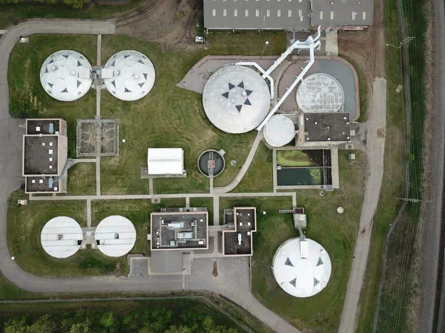
California’s Thermal Plan sets a 2.2 K (4 °F) maximum temperature increase for new cooling-water discharges into San Francisco Bay, according to the Open Engineering Inc preprint published in 2026. This is a thermal constraint on cooling-water discharge; it is not a blanket effluent-quality limit for sanitary wastewater or cooling-blowdown chemistry. The applicable permit must identify the receiving water, discharge point, temperature condition, and other requirements.
The same preprint shows why cooling-system selection can change the wastewater problem. In its modeled seawater-first case, variable-speed pumping held the temperature rise at 2.0 K, consumed 182–219 MWh, and pumped about 1.13 million m³ of Bay water annually, with PUE about 1.08 depending on pipe friction. The hybrid case with plain-plate stacks consumed 187–217 MWh and pumped about 27,000 m³ annually—about 41 times less Bay water and heat than the seawater-first case.
These results remain screening-level model outputs for a 270 kW server room. They are useful for identifying the relationship between heat-rejection design, pumping, withdrawal, and thermal discharge, but they do not establish the equipment duty for another data center.
| Modeled condition in the 2026 Open Engineering Inc preprint | Reported result | Engineering caveat |
|---|---|---|
| Seawater-first case with variable-speed pumping and 2.0 K rise | 182–219 MWh; about 1.13 million m³ pumped annually; PUE about 1.08 | Result depends on modeled pipe friction |
| Hybrid case with plain-plate stacks | 187–217 MWh; about 27,000 m³ pumped annually; about 41 times less Bay water and heat | Plain-plate stacks were modeled as much larger than first drawn |
| Counterflow-core sensitivity | A checked commercial core reached 81–85% effectiveness | Sensitivity evidence, not a universal performance guarantee |
| 24 °C supply setpoint | Pump runtime fell to about 4.4% of hours; contained rack inlets remained at or below 25.5 °C | Verify with a site-specific thermal model |
Heat-exchanger performance materially affects pumping and Bay-water use. At 0.60 exchanger effectiveness, described in the preprint as typical of some commercial cores, modeled pump runtime more than tripled. Raising the supply setpoint to 24 °C, within ASHRAE’s recommended range, reduced pump runtime to about 4.4% of hours in the model, while full cold-aisle containment kept rack inlets at or below 25.5 °C.
The preprint’s outdoor-air and seawater-loop costs were placeholders. Its screening payback of about 1.5–8 years at $0.125/kWh and 1–3.5 years at about $0.25/kWh therefore should not be copied into a San Francisco project budget without updated quotations and a site-specific model.
Build the Treatment Train from the Discharge Destination
The discharge destination determines the treatment objective, and the treatment objective determines the equipment train. A sanitary-sewer route begins with the local utility’s industrial-user or indirect-discharger requirements. Confirm limits for discharge volume, pH, metals, suspended solids, and local restrictions with the authority before specifying equipment; no generalized article can establish the applicable San Francisco permit criteria.
For internal cooling reuse, determine whether suspended solids, hardness, alkalinity, chlorides, treatment chemicals, and biological control exceed the cooling vendor’s limits. Basic clarification may be sufficient only if the characterized water and proposed chemistry remain within those limits. Where suspended solids, colloids, oil and grease, or flocculated material require removal, compare dissolved air flotation, clarification, and filtration by their actual removal duties rather than treating them as interchangeable.
An industrial DAF system for blowdown pretreatment is one separation option. HydropureWater DAF systems cover 4–300 m³/h across 13 standard models and are designed for suspended solids, FOG, oil and grease, and colloidal matter. Those specifications do not establish site suitability; the actual matrix, flow profile, and required performance must be confirmed before model selection.
Where pH adjustment, coagulation, flocculation, corrosion control, or specialty chemicals are required, evaluate a PLC-controlled chemical dosing system. HydropureWater automatic dosing systems are skid-mounted, pre-wired, factory-tested, and designed for precise injection. Chemical selection should follow jar or bench tests rather than generic dosing assumptions.
For microbial control, evaluate chlorine dioxide where an engineered installation suits the site. HydropureWater configurations range from 50 g/h to 20,000 g/h and are listed for industrial cooling loops and process wastewater. Confirm residual limits, contact conditions, chemical demand, and permit acceptance before selecting a generation capacity.
Where membrane protection or very low solids are required, compare ultrafiltration with conventional clarification. HydropureWater UF systems provide 2,000–40,000 L/h, use 0.03 micron PVDF membranes, remove bacteria, colloids, and suspended solids without chemicals, and accept turbidity up to 300 ppm. If reuse advances toward near-reuse quality, compare membrane bioreactor technology with simpler clarification and disinfection. HydropureWater MBR systems cover 10–2,000 m³/day and provide sub-1 μm filtration.
| Treatment objective | Potential equipment duty | Required design checks |
|---|---|---|
| Remove suspended solids, oil and grease, or colloids | DAF, clarification, or filtration selected by contaminant duty | Measured flow, solids/oil characteristics, required removal, residuals |
| Adjust pH or add treatment chemicals | Automatic chemical dosing with PLC control | Chemical demand, target range, injection point, controls interlocks |
| Control microbes | Engineered chlorine-dioxide system | Residual, contact time, demand, permit acceptance, safety controls |
| Protect downstream membranes or achieve low solids | Ultrafiltration | Influent turbidity, flow profile, membrane flux, cleaning waste |
| Advance toward near-reuse quality | MBR, potentially with additional treatment | Effluent specification, hydraulic variation, biology, fouling, residuals |
| Manage every non-sewer route | Sludge, concentrate, spent media, cleaning-waste, and chemical management | Disposal route, storage, tracking, and treatment of residuals |
Every non-sewer route also needs a residual-management step covering sludge, membrane cleaning waste, spent media, chemical inventory, and concentrate. The supplied research does not establish a universal concentrate-disposal method, so the selected route must be verified for the project.
Size Equipment from Test Data, Not Peak Cooling Load
Cooling megawatt capacity is not a defensible treatment-flow basis. The flow sent to a treatment unit depends on evaporation, makeup, blowdown control, cooling load, operating cycles of concentration, and the selected discharge or reuse route. Equipment sizing should follow measured hydraulic and contaminant data.
Create a sampling plan covering representative cooling loads, source-water conditions, chemical additions, seasonal changes, and normal cleaning events. Record flow and quality separately for blowdown, softener or reverse-osmosis reject if present, backwash waste, laboratory drains, and sanitary wastewater. Each stream needs its own peak, average, batch, and intermittent-flow profile.
Size clarification, filtration, and disinfection from verified hydraulic and contaminant data. Do not size DAF or MBR equipment from cooling megawatt capacity alone. Where a drain cannot be held during an equipment outage, identify whether storage, standby capacity, or an alternate route is required.
Use pilot or bench testing when the wastewater matrix is uncertain, reclaimed water is proposed, or chemical precipitation may change sludge characteristics. Confirm that the selected process handles representative variability rather than only a clean-water sample. A UV sterilizer may have a defined role in disinfection, but its sizing still depends on validated flow, transmittance, dose, and fouling conditions.
The supplied research contains no validated San Francisco data-center wastewater flow, blowdown chemistry, or equipment-price basis. Those inputs must be measured and quoted before procurement. The industrial ETP versus DAF selection guide can support option screening, but it cannot substitute for project data.
Compliance, Controls, and Ongoing Verification
A wastewater discharge permit or reuse specification must be converted into a compliance matrix before commissioning. The supplied research does not establish the applicable San Francisco permit limits, so the project record should identify the issuing authority, permit number, effective conditions, monitoring requirements, reporting deadlines, and responsible organization. Water Utility Report, updated 2026-04-14, identifies discharge volume, expected chemistry, pretreatment requirements, and whether the local wastewater system has assessed cumulative loads from multiple facilities as key questions.
Map every requirement to a parameter, monitoring method, frequency, responsible party, and corrective-action trigger. Conductivity or TDS can serve as operational indicators of concentration, but permit compliance still requires confirmation of metals, pH, suspended solids, treatment residuals, and any other specified parameters against the actual permit.
Trend blowdown flow and quality against cooling load, makeup chemistry, chemical consumption, and cycles of concentration. This separates normal concentration from source-water changes, excessive chemical addition, or process upsets. It also provides the operating record needed to demonstrate that pretreatment is functioning as designed.
For reuse, obtain written cooling-system compatibility limits and document cleaning, corrosion, scaling, and biological-control requirements before commissioning. Check the proposed treatment train against the required treatment valves, media, and replacement parts so the operating plan includes consumables and maintenance access rather than only the main vessels.
| Control objective | Monitoring or verification | Operational use |
|---|---|---|
| Permit compliance | Permit-defined parameters, methods, frequency, and reporting | Demonstrate compliance and trigger corrective action |
| Concentration control | Conductivity or TDS, cycles of concentration, and blowdown flow | Detect deviations from the intended cooling-water balance |
| Treatment performance | Suspended solids and target contaminant removal | Adjust chemical dose or verify separation performance |
| Reuse compatibility | Supplier water-quality limits, scaling, corrosion, and biological checks | Protect cooling equipment and maintain safe operation |
| Residual management | Sludge, concentrate, spent-media, and cleaning-waste records | Document storage, handling, and authorized removal |
Operating verification should continue after start-up. Trends must identify not only excursions but also changing source chemistry or residual accumulation that could erode treatment performance over time.
Procurement Checklist for a San Francisco Data Center
Issue a source-water and waste-stream characterization report before requesting a guaranteed-flow treatment proposal. The package should establish separate flows and chemistries for blowdown, sanitary and process wastewater, condensate, wash streams, reject water, and backwash waste, together with the intended destination and reuse specification.
Require each vendor to state design flow, duty cycle, contaminant basis, chemicals, residuals, control philosophy, footprint, utilities, and included pretreatment. Performance guarantees should be tied to the project’s measured influent and the applicable permit or reuse specification. A proposal based only on cooling load should be returned for clarification.
Confirm whether the offered DAF, UF, MBR, chlorine-dioxide, or other HydropureWater equipment is a standalone step or part of an integrated train. Review the UF system, integrated MBR system, and chlorine-dioxide generator against actual treatment functions to avoid duplicated pretreatment or chemical systems.
Include local utility and discharge-permit confirmation in the design basis, while recognizing that a generalized article cannot establish the applicable San Francisco permit limits. Compare lifecycle needs: membrane or media replacement, chemical consumption, sludge removal, operator attention, controls integration, utility requirements, and service support.
Require the bidder to identify what testing remains outstanding and which results could change the selected process, capacity, chemistry, or residual route. That avoids treating preliminary source-water data as guaranteed design evidence.
Frequently Asked Questions
What treatment does a San Francisco data center usually need for cooling-tower blowdown?
The required train depends on the destination and characterized contaminants. For sanitary sewer, confirm the utility’s applicable discharge criteria and whether pretreatment is required. For reuse, the cooling supplier’s water-quality limits determine the required solids, hardness, alkalinity, chloride, corrosion, scaling, and biological control. No research supplied for this article supports a universal San Francisco equipment package.
Can San Francisco data-center blowdown be reused instead of discharged?
Potentially, but only after site-specific evaluation. Confirm the available source-water chemistry, blowdown flow and variability, proposed reuse application, cooling-system limits, residual treatment, and monitoring requirements. Water Utility Report, updated 2026-04-14, notes that recycled source water changes the chemistry challenge and may increase pretreatment, corrosion-control, scaling-control, or monitoring needs.
Should a San Francisco data center buy DAF, UF, MBR, or chlorine dioxide?
Select by treatment function, not by product category. DAF addresses suitable floatable or particulate duties; UF provides low-solids separation; MBR combines biological treatment with membrane filtration; and chlorine dioxide provides an engineered disinfection function. Require the supplier to demonstrate that its proposed step handles the measured matrix and meets the destination specification.
What data is required to size a cooling-blowdown treatment system?
Request separate flow histories and water analyses for each stream, including blowdown, source water, sanitary and process wastewater, reject water, backwash waste, condensate, and wash streams. Include the chemical program, cycles of concentration, cooling-load range, cleaning events, and variability. Use bench or pilot testing when the matrix is uncertain or precipitation may affect residuals.
What permit and supplier-selection risks should a San Francisco data center avoid?
Do not accept a thermal-discharge study as an effluent permit, or a vendor guarantee based only on cooling load. For the budget decision, request a priced scope tied to measured flows and chemistry, including utilities, pretreatment, controls, residuals, consumables, maintenance, and disposal; the supplied research contains no project price basis. For supplier selection, require utility and permit confirmation, site-specific performance guarantees, controls integration details, and documented residual-management responsibilities before award.
Related Equipment
- industrial DAF system for blowdown pretreatment — specifications, capacity range, and technical data