Build the Ashgabat Water Balance Before Selecting Equipment
An Ashgabat data center needs a segregated, water-efficient treatment train for cooling-tower blowdown, sanitary sewage, process wastewater, and washdown. The priority is usually cooling blowdown because it contains concentrated salts and residual chemicals and can represent 20–40% of cooling-water intake. Genesis Water Technologies reports that actual blowdown may exceed theoretical calculations by 15–30%. Treatment should be sized from measured flow, conductivity, pH, suspended solids, temperature, hardness, silica, and chemical history. Filtration or flotation can prepare blowdown for non-critical reuse, while UF and RO may be required for higher-quality reuse. The final design must use verified Ashgabat discharge, water-source, and reuse requirements rather than assumed limits.
Start with a measured data center water balance, not an equipment catalogue. Account separately for incoming site water, cooling-tower makeup, evaporation, blowdown, filter backwash, cooling-chemical sludge, sanitary sewage, process wastewater, and equipment washdown. The objective is to identify where each stream originates, what it contains, where it currently goes, and whether the receiving route permits reuse. This is the core of a practical water-treatment parts, valves, and media package for the project.
Do not combine all wastewater into one treatment train. Cooling blowdown is a concentrated, chemically conditioned stream; sanitary sewage requires biological treatment; process wastewater may contain oils, metals, or cleaning chemicals; and washdown can carry suspended solids and dirt. Blending them can increase treatment load, obscure contaminant trends, and prevent reuse of a stream that is otherwise suitable for a defined purpose.
Install or confirm metering for makeup water, blowdown, and evaporation, and establish baseline conductivity, pH, and suspended-solids measurements. Genesis Water Technologies, in its article Why Cooling Tower Blowdown Is Your Hidden Opportunity, recommends this baseline because actual blowdown can exceed theoretical calculations by 15–30% because of unmeasured losses and emergency dumps.
The initial theoretical relationship is:
Blowdown-to-makeup ratio = 1 ÷ (cycles of concentration − 1)
Use that relationship to frame the design case, then validate it against metered site data. Before freezing the design, obtain verified information on the Ashgabat source water, seasonal supply reliability, intended receiving route, applicable local requirements, future expansion, and the planned reuse destination. Confirm whether reclaimed water will return to the cooling loop or serve sanitation, washing, landscaping, or another process.
| Balance input | Minimum engineering use | Evidence required before quotation |
|---|---|---|
| Cooling makeup, blowdown, evaporation | Calculate theoretical and measured operating balance | Meter history, operating logs, future cooling configuration |
| Conductivity, pH, suspended solids | Define contaminant baseline and control limits | Representative samples across operating conditions |
| Temperature, hardness, silica | Assess thermal impact, scaling, and reuse suitability | Cooling chemistry, makeup analysis, chemical-dosing records |
| Sanitary, process, and washdown flows | Assign separate treatment trains | Flow measurements, source inventory, discharge or reuse destination |
| Backwash and sludge | Design residual-management paths | Expected frequency, solids characterization, handling route |
Understand What Must Be Removed from Cooling Blowdown
Cooling-tower blowdown is the purge used to control accumulated dissolved solids, suspended material, and residual cooling chemicals as water evaporates. Its treatment requirements follow directly from the destination: discharge, washing, toilet flushing, irrigation, process use, and cooling-tower makeup impose different constraints on temperature, conductivity, solids, salinity, microbiology, and chemical content.
Warm blowdown can create thermal impacts, while its salts and treatment chemicals can increase the burden on receiving facilities. North Carolina State University’s 2026 article America’s Data Center Boom Puts New Pressure on Local Water Resources reports that discharging warm water can create thermal pollution and that blowdown can elevate salinity and carry biocides or anti-scalants. The responsible Ashgabat receiving route still has to be identified; the research supplied does not establish local discharge limits.
Characterize the feed before choosing equipment. Analyze silica, calcium carbonate, calcium sulfate, conductivity, hardness, suspended solids, pH, temperature, and the active chemical program. A suspended-solids problem calls for clarification; dissolved-salt and scaling control calls for membrane or precipitation processes; microbial control calls for a verified disinfection step. These are different problems and should not be collapsed into one generic treatment claim.
| Contaminant or condition | Relevant design concern | Treatment response to evaluate |
|---|---|---|
| Suspended solids and colloids | Filter fouling, media retention, membrane fouling | Media filtration, DAF, or UF pretreatment |
| Calcium carbonate, calcium sulfate, silica | Scale formation and membrane recovery limits | Controlled chemistry, antiscalant, RO, or a high-recovery salt-management design |
| Dissolved salts and conductivity | Discharge salinity and cooling-loop concentration | Blowdown recovery, RO, or controlled discharge |
| Residual biocide, dispersant, and corrosion inhibitor | Discharge impact, reuse suitability, membrane compatibility | Chemical-history review and destination-specific treatment |
| Temperature | Thermal impact on a receiving water body | Cooling, equalization, or discharge-route review |
| Microbiological growth | Health protection where reuse requires it | Validated disinfection rather than assumed adequacy |
Cycles of concentration, or CoC, are the ratio of dissolved-solids concentration in circulating water to that in makeup water. Genesis Water Technologies states that at 4 CoC, blowdown equals 25% of makeup volume, while at 6 CoC it equals 20%. Raising CoC without scaling and biological control is not a treatment solution: it can increase fouling, microbiologically influenced corrosion, and scaling damage. Any increase should therefore be linked to verified chemistry, control changes, and operating limits.
For suitable lower-grade reuse, evaluate a UF system for cooling blowdown pretreatment where suspended solids and colloids control the process. For oil-bearing, solids-rich wastewater, a DAF system for wastewater solids separation may be the relevant physical step. Neither decision should precede representative sampling and a defined reuse specification.
Choose a Treatment Route by Reuse Destination
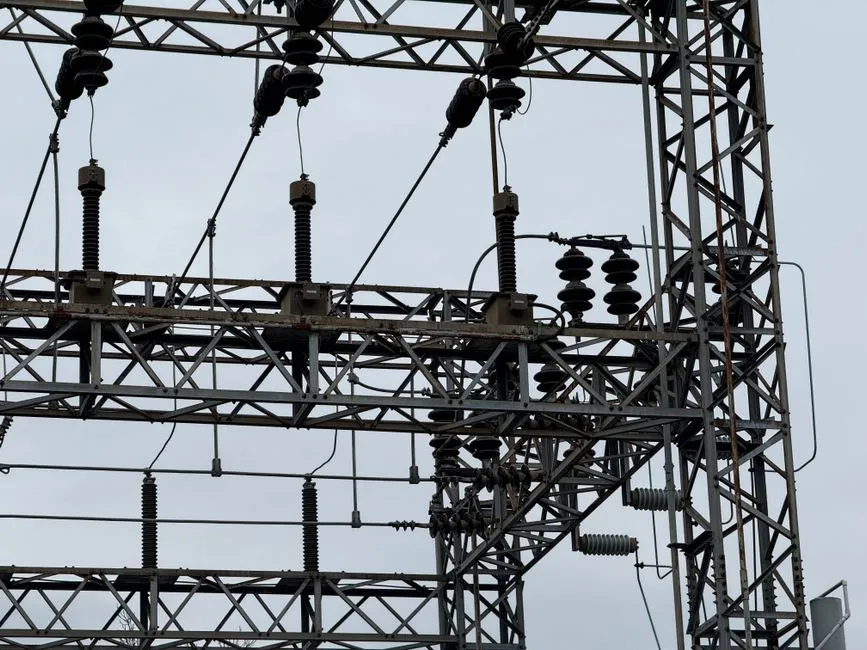
Choose the treatment train from the required end use, then work backward to the required water quality. Physical separation can prepare blowdown for suitable process uses; UF adds a higher solids-removal barrier; RO addresses dissolved salts; and disinfection addresses microbial criteria. The highest-complexity option is justified only when the receiving destination requires it and the concentrate has a defined management route.
For a physical-separation route, use media filtration or DAF for suspended solids, colloids, and entrained material. This may suit process washing or other non-critical destinations when the verified quality requirements can be met. It does not remove dissolved salinity merely because the water appears clear.
For an UF route, HydropureWater states that its hollow-fiber ultrafiltration system for cooling blowdown pretreatment handles 2,000–40,000 L/h, removes bacteria, colloids, and suspended solids without chemicals, and provides automatic backwash and air scour. For a data-center application, this published capacity is a supplier input to be matched against measured peak flow; it is not an Ashgabat design flow.
For an RO route, HydropureWater describes an industrial RO system for blowdown reuse with automated PLC control and recovery rates up to 95%. The feed chemistry still governs the result. IDE’s 2026 article Data Centers’ Water Reuse: Cooling Tower Blowdown reports that conventional brackish-water reverse osmosis commonly plateaus at 75–80% recovery because of scale-forming compounds such as silica, calcium carbonate, and calcium sulfate.
High recovery requires a different architecture. IDE describes separating salt removal from osmotic-pressure limits through controlled precipitation and advanced membrane operation. Its reported industrial installation operated at around 95% recovery and reduced permeate silica to about 1 mg/L. That is an application-specific result, not a transferable guarantee for Ashgabat. The project still needs a pilot or a chemistry-specific performance guarantee addressing silica, calcium carbonate, calcium sulfate, membrane scaling, concentrate disposal, and long-term operations.
| Route | Primary purpose | Decision condition | Residual to resolve |
|---|---|---|---|
| Media filtration | Remove suspended material | Destination permits physical treatment and adequate clarity | Spent media, backwash, and sludge |
| DAF | Separate suspended solids, colloids, oil, and grease | Feed contains floatable or settleable material | Float sludge and chemical residuals |
| UF | Provide a high-quality solids and bacteria-removal barrier | RO pretreatment or higher-quality reuse requires it | Backwash and membrane replacement |
| RO | Remove dissolved salts | Cooling makeup or another low-conductivity destination needs it | Concentrate, scaling, energy, and membrane renewal |
| High-recovery salt management | Increase recovery by controlling scale-forming salt removal | Makeup savings justify added complexity and operators | Precipitated salts and operational controls |
| Disinfection | Control microorganisms | The intended reuse or process has a microbial requirement | Disinfectant production, storage, dosing, and residuals |
Add disinfection only where the reuse or process specification requires microbial control. HydropureWater offers chlorine-dioxide configurations from 50 g/h to 20,000 g/h for industrial cooling loops and process wastewater through its chlorine-dioxide generator. The required generation rate, dose, contact condition, and residual limits must come from the design basis rather than the equipment range.
Do not specify advanced make-up reuse until representative testing addresses scaling, chemical compatibility, concentrate handling, membrane cleaning, and operator competence. A lower-complexity route may deliver a better project outcome if the intended reuse does not demand demineralized water.
Design Separate Wastewater Treatment Streams
Separate non-cooling wastewater by contaminant profile and destination. Mixing sanitary sewage with concentrated cooling blowdown imposes unnecessary biological and solids loads; combining oily process water with washdown can also complicate oil recovery and sludge handling.
Route sanitary sewage to a biological treatment train. HydropureWater states that its integrated MBR wastewater-treatment system handles industrial and municipal reuse projects from 10 to 2,000 m³/day and produces filtration below 1 μm. Verify the actual sanitary flow, peak factor, effluent destination, and local requirements before assigning equipment capacity.
For applicable process wastewater and washdown streams containing oil, grease, and suspended solids, provide physical separation upstream of biological treatment or discharge. HydropureWater states that its DAF system handles 4–300 m³/h and is designed for suspended solids, FOG, oil and grease, and colloidal matter. These published limits are product-envelope information, not a substitute for site flow and compositional data.
Use automatic chemical dosing where the process needs controlled coagulant, flocculant, pH adjustment, or specialty chemical addition. HydropureWater’s automatic chemical dosing for pretreatment should be specified around the required duty, tank arrangement, chemical compatibility, and control sequence. Do not prescribe a dose until jar or pilot testing establishes it.
Manage separated solids as a design stream. HydropureWater reports that its plate-and-frame filter presses cover filtration areas from 1 m² to 500 m² for industrial sludge dewatering. Dewatering performance still depends on sludge characteristics, feed rate, polymer use, cake handling, and the final disposal or reuse route.
| Stream | Default treatment route | Design input still required |
|---|---|---|
| Cooling blowdown | Filtration or DAF; UF/RO only where the reuse specification requires it | Complete chemistry, temperature, flow profile, and concentrate route |
| Sanitary sewage | Biological treatment with clarification or membrane separation as required | Flow, loading, effluent destination, reuse contact conditions |
| Process wastewater | Source-specific physical, chemical, and biological treatment | Complete constituent inventory and variation across operations |
| Equipment washdown | Settling, screening, and solids or oil separation | Cleaning chemicals, grit, oil content, and discharge route |
| Backwash and sludge | Thickening, dewatering, and authorized handling | Solids yield, dewatering test, cake destination, residual chemistry |
Check every proposed reuse for cross-connections and contact requirements. If reclaimed water enters a cooling loop, is used for flushing, or comes into contact with personnel, the applicable health and plumbing controls must be verified independently. The supplied research does not document the Ashgabat requirements for those applications.
Right-Size a Modular System for Ashgabat Operations
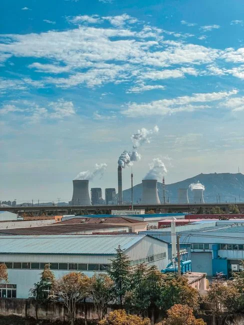
Size each treatment train from verified peak and average flows, expansion plans, operating redundancy, and the selected end-use specification. IT load alone does not establish wastewater flow: cooling configuration, cycles of concentration, weather, operating schedules, and process changes all affect demand.
Genesis Water Technologies identifies modular 100–300 GPM blowdown treatment systems as a practical scale for enterprise and colocation facilities. It also warns that hyperscale treatment approaches requiring reverse osmosis, ion exchange, and multi-stage filtration may be operationally and economically unsuitable for smaller sites. Match the chosen architecture to available staff, maintenance capability, and the facility’s actual scale.
Supplier comparisons should include local utility conditions, transport and installation access, ambient temperature, footprint, power, operator skill, remote monitoring, and local service capability. The Ashgabat project should also establish commissioning access, spare-part logistics, membrane or media delivery, and response time for critical failures.
| Procurement item | Information to request from each bidder | Acceptance basis |
|---|---|---|
| Duty and redundancy | Average and peak flow, expansion allowance, duty/standby philosophy | Measured site data and approved design cases |
| Process guarantee | Feed envelope, treated-water limits, recovery, availability | Defined end-use quality and test protocol |
| Controls | PLC functions, HMI, alarms, interlocks, data logging, remote access | Approved cause-and-effect matrix |
| Instrumentation | Flow, pressure, conductivity, differential pressure, membrane flux, temperature | Calibration and signal list |
| Residuals | Concentrate quantity and chemistry, backwash, sludge, chemicals | Documented receiving or disposal route |
| Operations | Training, manuals, preventive maintenance, spares, remote support | Commissioning and handover plan |
| Commercial | Ex-works scope, freight, installation, commissioning, warranty, renewal cost | Like-for-like total lifecycle comparison |
For a filtration package, review media, vessels, valves, controls, and service requirements using the water-treatment parts, valves, and media specification set. For RO, request membrane warranties, scaling projections, cleaning methods, concentrate-management details, replacement costs, and the minimum sustainable recovery for the proposed feed composition. Available RO and UF membrane and filter elements should be evaluated as part of the complete operating package, not as isolated consumables.
Require automatic PLC controls, flow and pressure instrumentation, conductivity monitoring, and differential-pressure or membrane-flux monitoring appropriate to the process. The supplier should submit alarm priorities, automatic isolation, fail-safe states, manual operating instructions, and clear shutdown logic. Complexity without operator support is a lifecycle liability.
Build the Business Case and Commissioning Plan
Calculate avoided costs using total cost of water rather than utility charges alone. Include freshwater, wastewater disposal, treatment chemicals, energy, labor, membrane replacement, sludge handling, and equipment renewal. Genesis Water Technologies reports that its described physical-treatment and reuse approach can reduce makeup-water demand by 15–25%, but the project-specific share must be supported by the measured balance and selected end use. Treat that published percentage as a reported approach, not an Ashgabat guarantee.
Use a staged rollout:
- Establish the measured baseline, including makeup, blowdown, evaporation, flow, and water quality.
- Repair leaks, remove unnecessary once-through cooling, and optimize controls before adding treatment capacity.
- Verify the active chemical program, scaling control, biological control, and sustainable cycles of concentration.
- Commission the selected treatment train against its guaranteed feed envelope and end-use specification.
- Qualify each reuse destination and measure actual consumption.
- Consider advanced cooling-loop make-up reuse only after the lower-complexity system and residual routes are proven.
Acceptance testing should reconcile metered makeup, evaporation, blowdown, treated-water output, concentrate or residual discharge, conductivity, pH, suspended solids, and reuse-water consumption. Include repeat tests under representative operating conditions rather than accepting a single short run. The commissioning report should close the balance and document any deviation from design assumptions.
Require operator training, a preventive-maintenance schedule, a critical-spares list, remote alarm support, and a response plan for media or membrane fouling and chemical-control upsets. If the project is in a water-stressed location, the data-center wastewater treatment planning for a water-stressed location provides a related decision framework, but its local assumptions must be replaced with verified Ashgabat inputs.
Frequently Asked Questions
What Ashgabat discharge limits and water tariffs should be used in the design?
The supplied research provides no universal Ashgabat discharge limits, water tariffs, or receiving-route conditions. Before final design, request written confirmation of the applicable requirements from the responsible authorities and the receiving utility or system. Also obtain the current freshwater charge, wastewater charge, and any reuse or discharge fees; without those inputs, no defensible project price or payback can be calculated.
Should the Ashgabat data center size treatment from IT load or measured wastewater flow?
Size from measured peak and average flows, future expansion, operating redundancy, and the end-use water-quality specification. IT load is a planning indicator, not a wastewater-flow measurement. Require flow profiling across cooling, sanitary, process, and washdown services before issuing an equipment schedule.
How should treatment suppliers be compared before selecting a system?
Compare suppliers using the same feed-water envelope and end-use specification. Ask each bidder for recovery guarantees, concentrate and sludge routes, controls, alarm logic, membrane or media consumption, local service, commissioning tests, warranty scope, and lifecycle costs. Treat published equipment capacities and recovery rates as product data, not project guarantees, until incorporated into a binding technical offer.
Is RO suitable for cooling blowdown reuse before pilot testing is completed?
Do not deploy RO or high-recovery treatment on the basis of a generic recovery figure. First obtain representative blowdown chemistry, including silica, calcium carbonate, calcium sulfate, conductivity, hardness, pH, temperature, suspended solids, and the chemical program. Then require scaling analysis and a pilot or feed-specific guarantee covering recovery, membrane cleaning, concentrate management, and long-term operation. The data-center cooling blowdown treatment workflow shows why the recovery destination and residual-management route must be settled before procurement.