What a Cavitation Air Flotation System Actually Does
A cavitation air flotation (CAF) unit is a rectangular clarifier in which micro air bubbles are generated inside the flotation cell by a cavitation aerator, rather than by saturating a pressurized side stream as a conventional DAF does. According to manufacturer data from SIGMADAF, the system removes suspended solids, oils, grease, and colloids from industrial wastewater; the equipment is rectangular, compact, and does not require air compressors, recirculation pumps, or pressure tanks to operate.
Air is drawn in from outside the vessel by a specially designed aerator and introduced pressurized into the cell, where contact with the wastewater generates micro bubbles that attach to suspended particles and float them to the surface (SIGMADAF). A skimmer sweeps the floated layer — oils, grease, and floated solids — into a sludge container, while heavier particles settle to the bottom of the cell and are drawn off to the same container. A portion of the clarified water is recirculated internally to keep internal surfaces free of sediment buildup (SIGMADAF).
CAF units are deployed in three flowsheet positions. They act most often as a pretreatment step ahead of biological or membrane treatment, but SIGMADAF also documents installations where the same equipment serves as a secondary clarifier after a biological stage, or as a tertiary polishing step for final clarification. The defining engineering question for any of these positions is the same: how are the design parameters — microbubble generation route, hydraulic residence time, surface loading rate, air-to-solid ratio, and cell geometry — set for the specific wastewater matrix being treated?
Core Cavitation Air Flotation Design Parameters
The design variables that govern CAF performance are the microbubble generation mechanism, bubble size distribution, air-to-water ratio, hydraulic residence time, surface loading rate, cell length-to-width ratio, and skimmer speed. These are the same families of operating parameters that TecnoLógicas catalogs for DAF systems, applied here to a cavitation-driven bubble route (S5).
The single biggest design differentiator is the bubble generation route. A CAF unit generates micro bubbles in situ by cavitation, which eliminates the saturator vessel, recycle pump, and air compressor that a conventional DAF requires to dissolve air under pressure (SIGMADAF). The academic reference point for cavitation-based bubble generation is the "effective parameters on generation of nanobubbles by cavitation method for froth flotation applications" thread, which is cited alongside the TecnoLógicas DAF review (S5). Standard commercial CAF systems are built for flow rates from 3 m³/h up to 250 m³/h; that is the design envelope a vendor will normally offer (SIGMADAF).
Any CAF skid must also be evaluated against the same effluent-quality parameters used to characterize DAF performance: COD, pH, turbidity, and TDS, as the Research Square soft-sensor study did for the DAF effluent drawn from an industrial plant's equalization tank (S1).
| Design parameter | What it controls | What the engineer must define |
|---|---|---|
| Microbubble generation mechanism | How micro bubbles are formed in the cell | Cavitation aerator sizing vs. pressurized recycle loop (S2, S5) |
| Bubble size distribution | Attachment efficiency to colloids, oil droplets, and fine solids | Target mean bubble size for the matrix (vendor-specific, S5) |
| Air-to-water (or air-to-solid) ratio | Carrying capacity of the bubble blanket | Air feed setpoint to the cavitation aerator (SIGMADAF, S2) |
| Hydraulic residence time | Time wastewater spends in the flotation zone | Cell volume ÷ design flow (S5) |
| Surface loading rate | m³ of flow per m² of flotation area per hour | Footprint-driven, compared against vendor rating (S5) |
| Cell length-to-width ratio | Flow distribution and skimmer reach | Geometry defined at bid stage (SIGMADAF, S2) |
| Skimmer speed | Float removal rate and surface renewal | Drive speed range (SIGMADAF, S2) |
| Effluent quality targets | Discharge compliance or downstream load | COD, pH, turbidity, TSS targets (S1) |
For comparison with a DAF system already on the market, the HydropureWater DAF system uses a pressurized recycle package to produce micro bubbles, and its rated envelope is 4–300 m³/h across 13 standard models.
CAF vs Conventional DAF: Design Parameter Trade-Off
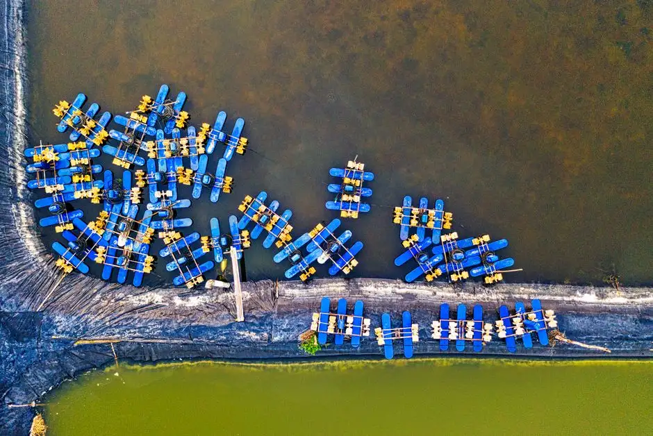
The engineering trade-off between CAF and DAF comes down to where the bubbles are made and what ancillaries that choice forces into the skid. In a CAF unit, micro bubbles are generated by cavitation inside the cell; in a DAF unit, air is dissolved into a pressurized side stream and released through nozzles in the contact zone (SIGMADAF; S5). That single choice cascades through every other parameter on the spec sheet.
CAF omits the air compressor, saturator or pressure tank, and recycle pump that a conventional DAF requires; the ancillary package reduces to the cavitation aerator, the skimmer drive, and a sludge draw-off (SIGMADAF). DAF skids scale in physical size with the saturator and recycle pump package, while the SIGMADAF documentation describes the CAF unit as rectangular and compact with no real siting constraints.
On capacity, the commercial envelopes are close. CAF is documented from 3 m³/h to 250 m³/h (SIGMADAF), while the comparable DAF envelope is 4–300 m³/h across 13 standard models on the HydropureWater product line. The practical question for a buyer evaluating both is not the upper flow number but what ancillary infrastructure comes with it: a DAF bid must include the air compressor room, the saturator, and the recycle pump head; a CAF bid does not.
On process control, CAF simplifies the control loop to aerator speed, skimmer speed, and sludge draw-off interval. A DAF loop adds saturator pressure, recycle flow rate, and air-saturation control as separate setpoints (S5; SIGMADAF). For a plant without compressed-air infrastructure or with a tight footprint, that control simplification is the decisive parameter.
| Design item | Cavitation air flotation (CAF) | Conventional DAF |
|---|---|---|
| Bubble generation route | In-cell cavitation aerator (SIGMADAF, S2) | Pressurized side stream dissolved under pressure, released through nozzles (S5) |
| Air compressor required | No (SIGMADAF, S2) | Yes (S5) |
| Saturator / pressure tank | None (SIGMADAF, S2) | Yes (S5) |
| Recycle pump | None (SIGMADAF, S2) | Yes (S5) |
| Footprint | Compact, rectangular, no siting issues (SIGMADAF, S2) | Scales with saturator and recycle skid |
| Capacity envelope | 3–250 m³/h (SIGMADAF, S2) | 4–300 m³/h across 13 standard models (HydropureWater DAF product line) |
| Primary control loops | Aerator speed, skimmer speed, sludge draw-off (SIGMADAF, S2) | Saturator pressure, recycle flow, air-saturation control, skimmer speed (S5) |
For a deeper trade-off on flotation versus oil-water separation, the DAF vs oil water separator comparison walks the same kind of side-by-side logic against a different competing technology.
Matching CAF Design to Wastewater Matrix
The application decision for a CAF unit is a flowsheet decision, and it starts with the wastewater matrix. For oily wastewater, CAF is a strong fit: the cavitation-generated micro bubbles attach to free and emulsified oil droplets and float them, which aligns with the established air-flotation-for-oil-separation literature reviewed in Wang et al. and applied industrially in the SIGMADAF CAF unit (S2; S4).
For food processing, pulp and paper, and textile effluent, CAF is commonly deployed because the unit handles suspended solids, FOG, and colloidal loads without a compressor-driven saturation system — a fit consistent with the food-processing, pulp and paper, and textile applications documented for the HydropureWater DAF product line and the SIGMADAF CAF line (S2; S6).
For metalworking and petroleum streams, the CAF unit fits as a pretreatment step to strip free oils and floatables ahead of a chemical or biological stage, occupying the pretreatment position that SIGMADAF documents for its commercial deployments. For pharmaceutical and other high-strength COD streams, the unit is more often placed downstream of an equalization tank as a polishing or pretreatment step rather than as a primary clarifier, which is consistent with how the Research Square DAF study drew its DAF feed from the equalization tank of an industrial wastewater treatment plant (S1; S2).
In practice this means the typical flowsheet is equalization → coagulation or flocculation → CAF → downstream biological or membrane step, with the CAF retention time set by how variable the upstream feed is. The pharmaceutical wastewater cavitation air flotation guide walks through one version of that flowsheet for a high-COD matrix.
Sizing Checklist Before Specifying a CAF Unit
Before a CAF purchase specification is issued, the engineer should pin down five input categories so bids from different vendors are comparable. The first is design flow in m³/h plus peak hourly flow, checked against the 3–250 m³/h commercial CAF envelope that SIGMADAF publishes (S2). A design flow near the upper end of that band will require the vendor to confirm hydraulic residence time at peak, not just at average.
The second category is influent quality. The same parameter set the Research Square DAF study used to characterize DAF effluent — COD, pH, turbidity, and TDS — should be collected at the upstream equalization tank so the CAF vendor can quote against the same influent definition (S1). Oil and grease, TSS, and temperature should be added for any matrix with FOG or emulsified oil load.
The third is the required effluent quality and the position the CAF unit occupies in the flowsheet. SIGMADAF documents CAF as pretreatment, secondary clarification, or tertiary polishing, and the residual load the downstream step must handle changes with that position. The fourth is available footprint; the compact rectangular CAF footprint is a documented design advantage over DAF skids (SIGMADAF), so the bid should ask for a plan-view footprint rather than a rated flow alone.
The fifth is utility availability. Because a CAF unit has no compressed-air demand and no recycle pump, the electrical supply and sludge handling downstream of the unit — typically a filter press such as the HydropureWater plate and frame filter press fed by an upstream automatic chemical dosing system — are the only utility interfaces to confirm (SIGMADAF).
| Input category | What to request | Why it matters |
|---|---|---|
| Design and peak flow | m³/h average and peak | Must fall inside the 3–250 m³/h commercial envelope (SIGMADAF, S2) |
| Influent quality | TSS, oil & grease, COD/BOD, pH, temperature | Same parameter set used to characterize DAF performance (S1) |
| Effluent targets | TSS, oil & grease, COD limits | Sets the residual load for the downstream step (S2) |
| Footprint | Plan-view dimensions for the cell | CAF compact footprint is a documented advantage (S2) |
| Utilities and sludge handling | Electrical load, sludge routing to a dewatering device | CAF has no compressed-air demand (S2); sludge typically goes to a filter press fed by a chemical dosing skid |
Frequently Asked Questions
What microbubble generation mechanism should a CAF specification require?
The specification should require in-cell cavitation, not pressurized air dissolution. SIGMADAF documents that the CAF unit generates micro bubbles inside the cell by drawing air in through a cavitation aerator, with no air compressor, saturator, or recycle pump required. Any vendor that quotes a saturator, recycle pump, or air compressor in the bid is bidding a DAF, not a CAF.
What capacity band should a CAF bid be requested against, and how does it compare with DAF?
The commercial CAF envelope is 3 m³/h to 250 m³/h (SIGMADAF, S2). The HydropureWater DAF system covers 4 m³/h to 300 m³/h across 13 standard models. If the design flow is outside 3–250 m³/h, the engineer should request a confirmed lead time for a custom unit rather than assume a standard model will cover it, and should ask the vendor to quote hydraulic residence time at peak hourly flow, not just at average.
What influent and effluent parameters should be pinned down before issuing a CAF spec?
Collect TSS, oil and grease, COD, BOD, pH, and temperature at the upstream equalization tank, and define TSS and oil and grease targets at the CAF outlet. The Research Square DAF soft-sensor study used COD, pH, turbidity, and TDS from the effluent of the equalization tank as its model inputs (S1); mirroring that set in the CAF spec keeps the influent definition consistent with how DAF performance is normally reported.
What should a buyer check when comparing CAF vendors and DAF retrofit options?
The buyer should ask each vendor to provide a plan-view footprint, a confirmed model within the 3–250 m³/h CAF envelope (SIGMADAF) or the 4–300 m³/h DAF envelope (HydropureWater DAF system), a list of ancillaries (compressor, saturator, recycle pump — DAF only), and a hydraulic residence time at peak flow. Comparing bids on those four items, rather than on rated flow alone, is the cleanest way to keep a CAF proposal and a DAF retrofit on the same basis.
Related Equipment
- HydropureWater DAF system — specifications, capacity range, and technical data
- HydropureWater automatic chemical dosing system — specifications, capacity range, and technical data
- HydropureWater plate and frame filter press — specifications, capacity range, and technical data