Why Cavitation Air Flotation Exists: The DAF Limitations That Drive the Design
Dissolved air flotation has been the workhorse of industrial wastewater pretreatment for decades, but its design chain is exactly what creates its limits. The process requires chemical flocculation of the suspended solids, pressurised dissolution of air into a side stream, and release of that stream through small-bore nozzles to form a bubble blanket that floats the floc to the surface for skimming (IPPTA, 1995, Finn). Four pieces of hardware are therefore non-negotiable on any conventional DAF unit: an air compressor to charge the saturator, a recirculation pump to feed it, a pressure vessel to hold the air–water mixture at saturation pressure, and the release nozzle train that breaks the saturated water into microbubbles. Each of these four items introduces a well-known failure mode — compressor and recirc energy cost, saturator maintenance, and nozzle blockage from particulates or polymer residue.
Beyond the hardware list, there is a thermodynamic ceiling that no amount of chemistry can raise: DAF can only float as much mass as it can physically dissolve. The volume of air that a DAF saturator can hold in solution is bounded by Henry's law and the operating pressure of the vessel. On high-SS industrial streams — tanneries, pulp and paper mill effluents, food and dairy — that ceiling is reached before the bubble blanket has enough buoyancy to lift all the floes, so a fraction of the floc escapes with the underflow as "sinkers". The cavitation air flotation design is the direct engineering response: no compressor, no recirc pump, no pressure vessel, no nozzles; air is drawn in at atmospheric pressure through a draft tube and broken into a microbubble blanket by an impeller-driven cavitation zone inside a rectangular tank. The full operational comparison against a packaged HydropureWater DAF system becomes clearer in the trade-off table later in this guide, but the design philosophy is set here: CAF swaps DAF's dissolved-air hardware for a cavitation impeller, gaining buoyancy headroom and removing the saturation ceiling.
Design Criterion 1 — Coagulant and Flocculant Program
Per IPPTA (1995, Finn), the first of the four CAF design criteria — and the one the source calls the most cost-sensitive — is the chemical program. Two reagents are required, dosed in sequence, and the sequence itself is a hydraulic specification as much as it is a chemistry specification. Step one is an inorganic coagulant, added to neutralise the electrostatic repulsion that keeps colloidal and fine suspended particles dispersed in the wastewater. Coagulants work on charge destabilisation, and charge destabilisation is not instantaneous: the dose needs residence time in a mixed zone before the second reagent is introduced. Step two is an organic flocculant, usually a high-molecular-weight polyelectrolyte, which is dosed at a separate downstream point and agglomerates the destabilised particles into floes that are large enough to attach to microbubbles. Finn warns that the flocculant "tends to cause floc formation almost instantaneously" on contact, which means the dosing points and the inter-stage pipe lengths are not free variables — they are part of the design.
The coupling between chemistry and hydraulics is what makes the chemical program the controlling criterion. The downstream cavitation chamber is sized in seconds, not minutes, because floc formation is expected to be complete by the time the flow reaches it. If the coagulant is under-dosed, the flocculant builds weak, re-fragmenting floes and the unit produces "broken floc" carryover in the clarified overflow. If the flocculant is over-dosed, the floes become slimy, trap too much water, and pull the beach scraper drive beyond its torque budget. For a buyer, the operational test of whether a vendor has actually engineered the chemistry is simple: ask for the recommended coagulant/flocculant pair and the dosing-point layout for the specific effluent you are treating. A generic "use a cationic polymer" answer means the vendor has not bench-tested the chemistry, and it is the most common reason CAF units underperform in the field (IPPTA, 1995, Finn). Pairing the chemical program with an HydropureWater automatic chemical dosing system preserves the dosing-point discipline during flow swings.
Design Criterion 2 — Cavitation Chamber, Aerator and Microbubble Generation
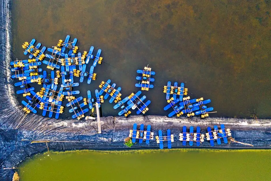
The cavitation chamber is the part of a CAF unit that has no analogue in a DAF, and the part that defines the air budget for the whole process. Per IPPTA (1995, Finn), wastewater is added at a steady rate into a rectangular cavitation chamber at one end of the tank. The flocculant is dosed at the inlet. Air is introduced below the water inlet pipe so the entire air flow is entrained into the wastewater rather than short-circuiting to the surface. The chamber is sized for a floc retention time of 2–4 seconds, which is an order of magnitude shorter than the downstream flotation chamber and must be preserved in any scale-up.
Air enters the chamber through a patented cavitation aerator: a hollow, four-pronged impeller rotating at 1,700 rpm and driven by a simple 2 or 3 hp motor (IPPTA, 1995, Finn). The geometry of the impeller creates a localised cavitation zone whose pressure drop draws ambient air down a draft tube — the same vacuum that pulls air in also pulls a natural recycle from the flotation chamber back into the cavitation zone, equal to 20–25% of the total hydraulic flow, without any external pump. The combination of cavitation and shear collapses the entrained air into a microbubble band of "reasonable uniform" size between 500 Nm and 1 mm. The unit Nm in the 500 Nm figure denotes a nanometre-class bubble; this is not a typographical error. The impeller emits air at approximately 1 ft³/s, which IPPTA (1995, Finn) reports as roughly four times the total amount of air that a DAF saturator can physically dissolve in the same water.
| Parameter | Value | Source |
|---|---|---|
| Cavitation chamber HRT (floc maturation) | 2–4 s | IPPTA, 1995, Finn |
| Impeller speed | 1,700 rpm | IPPTA, 1995, Finn |
| Drive motor, cavitation aerator | 2 or 3 hp | IPPTA, 1995, Finn |
| Microbubble size band | 500 Nm to 1 mm | IPPTA, 1995, Finn |
| Air emission rate from impeller | ~1 ft³/s | IPPTA, 1995, Finn |
| Natural recycle, flotation → cavitation | 20–25% of hydraulic flow | IPPTA, 1995, Finn |
Design Criterion 3 — Flotation Chamber Sizing and Effluent Laundering
The third design criterion (IPPTA, 1995, Finn) is the flotation clarification stage itself. The CAF system allows for 17 minutes of retention time in the flotation chamber, which the source describes as the optimum time for both clarified-water quality and surface-sludge thickening. In practical terms, the chamber volume in cubic metres equals the design flow in cubic metres per hour multiplied by 17 minutes and divided by 60. An engineer evaluating a vendor proposal can back-calculate from the quoted flow and the published tank dimensions to confirm the 17-minute criterion is being met; if the published residence time falls below about 12–13 minutes at the nameplate flow, the unit is being undersized relative to the IPPTA design intent.
Hydraulic control in the flotation chamber is done by the discharge weir, not by valves. The weir is adjustable so the same tank geometry can be tuned to the sludge blanket thickness that the upstream chemistry actually produces on a given effluent. Clarified effluent passes under the angled beach, over the weir, and into a discharge chamber; floated sludge is conveyed up the beach by the scraper system described in the next criterion. The 17-minute retention is also why the chamber is sized in minutes while the cavitation chamber is sized in seconds: the cavitation zone is a reaction vessel, the flotation zone is a settling vessel, and conflating the two is a common error in vendor scope.
Design Criterion 4 — Solids and Liquids Separation at the Beach
The fourth and final design criterion (IPPTA, 1995, Finn) is the mechanical separation of floated sludge from clarified water at the discharge end of the flotation chamber. Solids are continuously pulled over an angled beach by scrapers and deposited into a side channel, where a screw auger continuously dewaters or transfers the sludge for off-site handling. Both the scrapers and the auger are driven by the same ½ hp geared motor, which is a very small motor for a unit that can handle flows up to 150 m³/h — the small motor is itself evidence of how little work the mechanical removal stage has to do once the chemistry and air supply are correct.
Two design choices on the beach determine whether the floated mass leaves the tank as a manageable sludge or re-suspends into the clarified water. First, the variable-speed drive on the scraper/auger motor is the operator's primary control for surface-sludge thickness; combined with the weir setting for hydraulic head, it sets the steady-state blanket depth. Second, the beach geometry has to be steep enough that scraper torque is not exceeded at the design flow, but shallow enough that the sludge does not slide back under the scraper. The failure mode this design prevents is the accumulation of float until it is forced back into the clarified water — a "sinkers" event in reverse — which the source lists as a principal way CAF units underperform in the field. The downstream dewatering device, such as a HydropureWater plate and frame filter press, then handles the thickened sludge stream the beach delivers.
Consolidated CAF Design Parameter Table
The table below consolidates the parameter set a process engineer can lift directly into a specification or a vendor-evaluation spreadsheet. The 1995 IPPTA figures are the original design-criterion values from Finn's paper; the commercial-range figures come from published vendor data and are presented as commercial-unit benchmarks rather than as additional IPPTA evidence.
| Design parameter | Value | Source |
|---|---|---|
| Cavitation chamber HRT (floc maturation) | 2–4 s | IPPTA, 1995, Finn |
| Flotation chamber HRT | 17 min | IPPTA, 1995, Finn |
| Microbubble size band | 500 Nm to 1 mm | IPPTA, 1995, Finn |
| Air emission rate, cavitation impeller | ~1 ft³/s | IPPTA, 1995, Finn |
| Cavitation impeller speed | 1,700 rpm | IPPTA, 1995, Finn |
| Drive motor, cavitation aerator | 2 or 3 hp | IPPTA, 1995, Finn |
| Drive motor, scraper/auger | ½ hp geared, variable speed | IPPTA, 1995, Finn |
| Natural recycle (flotation → cavitation) | 20–25% of hydraulic flow | IPPTA, 1995, Finn |
| Power-per-flow benchmark | 2½ hp to 20 m³/h; 3½ hp to 150 m³/h | IPPTA, 1995, Finn |
| Commercial unit flow range | 3–250 m³/h | SIGMADAF product data (S3) |
CAF vs DAF: A Design Trade-Off Table
For a procurement-side reader, the practical question is not "which technology is better" but "which design choices match this effluent and this site." The table below is a side-by-side at the design-criterion level, not at the marketing level, drawn from the limitations list Finn (IPPTA, 1995) gives for DAF and the design response he documents for CAF.
| Design element | DAF | CAF | Source |
|---|---|---|---|
| Air source | Compressor + pressure-vessel saturation | Draft tube + cavitation impeller at atmospheric pressure | IPPTA, 1995, Finn |
| Recirculation | Pressurised recirc pump loop | 20–25% natural recycle via the same impeller vacuum | IPPTA, 1995, Finn |
| Air quantity available | Bounded by dissolved-air saturation | ~1 ft³/s from the impeller, ~4× what DAF can dissolve | IPPTA, 1995, Finn |
| Bubble size | Tens to hundreds of micrometres from nozzle release | 500 Nm to 1 mm band from cavitation + shear | IPPTA, 1995, Finn |
| Blockage risk | Nozzle plugging, routine maintenance | No nozzles in the flow path | IPPTA, 1995, Finn |
| Energy budget | Compressor + recirc dominate motor list | 2½ hp at 20 m³/h; 3½ hp at 150 m³/h | IPPTA, 1995, Finn |
| Failure mode in field | Nozzle blockage, saturation ceiling on high-SS | Sinker carryover if chemistry is wrong | IPPTA, 1995, Finn |
The trade-off is therefore a clean exchange: DAF trades the absence of moving parts in the contact zone for a saturation ceiling and a hardware chain (compressor, recirc, pressure vessel, nozzles) that has to be maintained. CAF trades the mechanical simplicity of a saturator for the maintenance simplicity of an impeller and gains buoyancy headroom. On high-SS streams (tannery, pulp and paper, food, dairy) the buoyancy headroom is what makes the difference between a unit that meets discharge consent and one that does not, which is why these are the canonical CAF applications. Where a project has tight floor space, no compressor room, and a hot effluent stream that can be recycled (pulp and paper is the textbook case), a HydropureWater DAF system comparison is still worth running on flow and footprint, but the design headroom argument usually points back to CAF.
Documented Removal Performance on Industrial Effluents
General performance band from IPPTA (1995, Finn): with the correct chemical program, SS removal above 90% is expected and well above 95% is common. FOG removal is described as "equally, if not more, efficient" as SS removal. BOD removal depends on the SS-to-total-BOD ratio of the feed; 40–50% is typical, and more than 70% is achievable when feed SS is high. COD removal percentages are reported as slightly higher than the corresponding BOD removals. The four published case results below are the benchmarks an engineer can use to anchor their own design assumptions instead of relying on vendor brochures.
| Effluent | SS removal | FOG removal | BOD removal | COD removal | Source |
|---|---|---|---|---|---|
| Tannery | 97% | 96% | 49% | 64% | IPPTA, 1995, Finn |
| Dairy | 80% | — | 60% | 57% | IPPTA, 1995, Finn |
| Textile | 97% | — | 55% | 50% | IPPTA, 1995, Finn |
| Food processing | — | 97% | 44% | — | IPPTA, 1995, Finn |
Two design lessons fall out of the case data. Where the discharge target is FOG compliance (food, dairy), the 96–97% FOG removal numbers let the engineer size primarily on the FOG figure rather than on the SS figure. Where the target is reuse-water make-up — common in pulp and paper — the higher COD reduction in the tannery case (64%) is the more relevant benchmark than the BOD figure, because reuse streams are usually polished for COD rather than BOD. The source also notes that the dairy SS removal was capped at 80% only because the operator chose a reduced flocculant dose; the same unit had reserve capacity to push higher if consent required it. For a packaged treatment train that includes biological polishing, the HydropureWater integrated water purification architecture pairs the CAF pretreatment with downstream stages sized to the residual load.
How to Use These Criteria in a Vendor Evaluation
Translating the four design criteria into an RFQ turns the technical specification into a procurement checklist. The questions below are the ones a buyer should put in front of every vendor before accepting a quote.
- Ask each vendor for the cavitation-chamber HRT and the flotation-chamber HRT at the quoted design flow, and check both against the 2–4 s and 17 min numbers from IPPTA (1995, Finn).
- Request the microbubble size band the aerator produces and the air-to-water ratio at the design point. Vendor silence on this is a red flag — the air budget is what separates a working unit from an under-sized one.
- Confirm motor sizing. The IPPTA benchmarks are 2½ hp at 20 m³/h and 3½ hp at 150 m³/h; significantly larger motors imply DAF-style compressors or recirc pumps are hidden in the scope, which contradicts the CAF design philosophy.
- Request the recommended coagulant/flocculant pair and the dosing points for the specific effluent. A generic chemical program usually means the vendor has not bench-tested the chemistry on this wastewater.
- Confirm the beach/auger sludge-removal package and the variable-speed drive. Absence of either is the most common reason floated sludge re-suspends and undermines clarified-water quality.
- Cross-check the proposed flow against the commercial capacity range of 3–250 m³/h (SIGMADAF, S3) and against the typical 4–300 m³/h band of comparable DAF units (HydropureWater, S6) when comparing quotes on a like-for-like flow basis.
The cross-check between vendor flow ranges is where procurement and engineering meet on the same numbers. The 2026 DAF vs clarifier factory guide for mining and metals wastewater shows how the same comparison is run on a different effluent matrix, and the same six-question checklist applies.
Frequently Asked Questions
What is the single most important cavitation air flotation system design criterion?
Per IPPTA (1995, Finn), the chemical program is described as the first and most cost-sensitive of the four criteria, because the downstream cavitation, flotation and sludge-removal stages are all sized around the floc the chemistry produces. A well-sized cavitation chamber will still underperform if the floc is weak or slimy.
How does CAF design differ from DAF when sizing for a high-SS stream?
DAF is bounded by dissolved-air saturation and therefore struggles above a few thousand mg/L SS regardless of chemistry. CAF emits roughly 1 ft³/s of air from the cavitation impeller — about four times the air DAF can dissolve in the same water (IPPTA, 1995, Finn) — so the buoyancy headroom needed for high-SS streams is built into the design rather than added on with chemistry.
What power supply does a CAF unit need?
IPPTA (1995, Finn) specifies a 2 or 3 hp motor on the cavitation impeller and a ½ hp geared motor on the scraper/auger, giving a total installed power of 2½ hp at 20 m³/h and 3½ hp at 150 m³/h. Commercial units such as the SIGMADAF CAF range (S3) are offered from 3 m³/h to 250 m³/h, so a buyer should request the motor list and the simultaneous demand factor rather than the nameplate sum.
How much does a cavitation air flotation system cost in 2026?
The supplied research does not contain pricing data, so a dollar figure should be requested directly from vendors on a flow-rate, material-of-construction and sludge-disposal basis. A useful first benchmark is to compare $/m³·h of nameplate capacity against a comparable DAF quote on the same effluent and the same discharge consent, so the comparison is not biased by tank material or scope inclusions. The downstream sludge-dewatering train — covered in the 2026 filter press design guide for food processing wastewater — should be costed separately and added to the CAPEX before the two technologies are compared.