
Why Kawasaki Data Centers Need a Dedicated Blowdown Treatment Plan
Kawasaki's humid temperate climate and its position on the Tama/Tone system create a blowdown engineering problem that does not map onto the U.S. arid-site guidance dominating the top search results. Evaporation rates are lower than Phoenix or Loudoun County, so per-MW water loss is more modest, but cooling-tower operating hours are near-continuous for high-density compute loads, so the blowdown stream is a 24/7 discharge rather than a peak-summer peak (Sprenger, NC State, 2026-09). Makeup water typically comes from the Tama/Tone system or the Kawasaki municipal industrial supply, both of which carry moderate hardness and silica that fix the practical ceiling on cycles of concentration (COC) before scaling trips the tower.
Discharge routing sets the design envelope. Sewer discharge runs through Sewerage Law pretreatment rules enforced by the local POTW; direct discharge to Tokyo Bay — an enclosed, salinity-stressed receiving water — is the harder permit case, governed by the Water Pollution Control Act and the Kawasaki City ordinance. Hyperscale benchmarking puts the upper end of facility water demand at 5 MGD for the largest U.S. sites (Saha, UGA CAES TP-121, 2026); a Kawasaki hyperscale envelope is comparable in scale, and a single site's annual blowdown stream is therefore not a minor utility-side stream. The treatment train must be designed for Japanese source water, Japanese permit limits, and a humid-temperate operating profile rather than a generic arid U.S. tower.
What Is Actually in Cooling-Tower Blowdown
Blowdown is the controlled purge of recirculating cooling-tower water that keeps dissolved solids below scaling and corrosion thresholds as pure water evaporates from the tower (Saha, UGA CAES TP-121, 2026). It is not a dilute stream of the makeup water; it is the makeup water concentrated by the operating COC, plus every chemical dosed into the loop and every metal ion stripped from the wetted metallurgy.
Per UGA Extension (Saha, 2026) and EPA blowdown guidance, the stream carries concentrated salts, hardness ions, silica, biocides, corrosion inhibitors, and trace heavy metals. Biocides of concern split into oxidizing types — chlorine, bromine — and non-oxidizing types such as isothiazolones and DBNPA; their breakdown products carry through to the discharge (Saha, 2026, qualitative). Sprenger (NC State, 2026-09) explicitly flags two blowdown-specific impacts: elevated salinity and chemical-additive carry-through, including biocides and anti-scalants. At higher COC, the same ion mass is discharged in a smaller volume — a trade-off that directly sizes the downstream treatment train.
| Pollutant family | Source in the cooling loop | Treatment implication |
|---|---|---|
| Hardness (Ca, Mg) | Makeup water concentration × COC | Softening or side-stream RO to prevent CaCO₃ / CaSO₄ scale |
| Silica | Makeup water; concentrates at high COC | Limits maximum COC; RO or ion-exchange polishing |
| Oxidizing biocides (Cl₂, Br₂) | Dosed for microbial control | Dechlorination or GAC before RO; residual ClO₂ for barrier |
| Non-oxidizing biocides (isothiazolones, DBNPA) | Dosed for microbial control | Often pass through to discharge; advanced oxidation if limits tighten |
| Corrosion inhibitors / anti-scalants | Dosed to protect metallurgy | Carry-through; GAC or AOP removal before reuse or sensitive discharge |
| Trace heavy metals | Stripped from wetted metallurgy | Ion-exchange polishing or precipitation before sewer or surface discharge |
Japanese Regulatory Framework Kawasaki Operators Must Meet
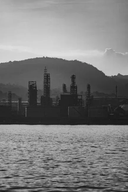
Cooling-tower blowdown in Kawasaki is regulated under a layered stack, and the applicable limits depend on where the stream is sent. Direct discharge to Tokyo Bay or to local rivers triggers the Water Pollution Control Act (Act No. 138 of 1970, as amended) national effluent standards, plus any stricter prefectural or Kawasaki-city ordinance values. Sewer discharge is governed by the Sewerage Law and the Kawasaki City Sewerage Ordinance, which impose pretreatment limits the POTW can enforce above national defaults — the same way U.S. pretreatment programs stack on top of Clean Water Act limits (Saha, 2026, EPA parallel).
Blowdown is treated as industrial wastewater in Japan, not as sanitary discharge, which puts the operator into the same permit class as a plating shop or a chemical plant. Reuse applications — cooling makeup, landscape irrigation, toilet flushing — are voluntary but can trigger additional targets such as JWRC reuse guidelines when the operator is claiming water-reuse credits or corporate water-stewardship metrics. The numerical ordinance values change as Kawasaki City updates its Water Quality Conservation Section rules; therefore, the engineering step before any equipment specification is to request the current ordinance values directly from the city.
Designing the Treatment Train: From Pre-Filtration to Polishing
The unit-process chain follows source-water chemistry on one end and the discharge target on the other. The sequence below is the order a Kawasaki engineer should walk when sizing equipment.
- Pre-filtration. Multi-media filtration drops suspended solids and protects downstream units; an SDI reduction to RO-feed levels is the typical target, consistent with the depth-filtration step in the S1 reuse train (Cartagena Vaca et al., 2026). A multi-media pre-filtration for blowdown is the conventional first stage.
- Softening or dealkalization. Sodium-cycle softening or dealkalization lifts allowable COC by roughly 1.5–2× before scale trips the tower; the trade-off is brine generation that has to be managed downstream. A twin-tank industrial softener to lift cycles of concentration is the workhorse option for this stage.
- Side-stream RO. A fraction of the recirculating water is bled through RO and the permeate returned to the loop; the concentrate becomes a smaller, more concentrated blowdown. This is the UF+RO-equivalent path identified in the S1 reuse LCA, with the highest energy intensity but the lowest blowdown volume and the highest COC. A side-stream RO on the blowdown loop is the primary lift.
- Biocide management. Oxidizing biocides are reduced with activated carbon or chemical dechlorination (typically sodium bisulfite) before RO feed; non-oxidizing biocides typically pass through to discharge and may need advanced oxidation if ordinance limits tighten.
- Polishing. Activated carbon for trace organics, ion exchange for residual hardness slip, and a microbial barrier — UV or ClO2 polishing before sewer discharge — are the conventional finishing steps. Antiscalant and pH trim on the RO feed is handled with PLC-controlled chemical dosing for antiscalant and pH trim.
| Stage | Unit process | Function | Design driver |
|---|---|---|---|
| 1 | Multi-media filter | Suspended solids, SDI reduction | RO feed SDI < 3 |
| 2 | Softener / dealkalizer | Hardness removal | Target COC and silica limit |
| 3 | Side-stream RO | Dissolved solids reduction; blowdown minimization | Recovery vs. energy trade-off |
| 4 | GAC / dechlorination | Oxidizing biocide and chlorine removal | RO membrane tolerance |
| 5 | Polishing (IX, UV, ClO₂) | Residual hardness, microbial barrier | Discharge target (sewer vs. reuse vs. surface) |
The COC lever runs across every stage. Rising COC cuts blowdown volume and chemical draw but pushes scaling chemistry toward silica and calcium sulfate, which softening alone cannot manage — that is where side-stream RO earns its place. Sprenger (NC State, 2026-09) frames the underlying point clearly: a data center's water demand never sleeps, so any reduction in blowdown volume that the chemistry allows is a reduction in 24/7 discharge load.
Three Kawasaki Scenarios: Sewer Discharge, On-Site Reuse, or ZLD
The same blowdown stream resolves into three different equipment trains depending on the disposal target. Choosing between them is a permit-and-cost decision, not a chemistry decision — the chemistry is fixed by the makeup water and the operating profile.
| Scenario | Treatment train | CAPEX profile | OPEX profile | Permit exposure |
|---|---|---|---|---|
| A — Sewer discharge | Sedimentation + multi-media filtration + dechlorination; minimal biocide polishing | Lowest | Driven by freshwater makeup and Sewerage Law compliance monitoring | Sewerage Law pretreatment; ordinance can tighten |
| B — On-site reuse for cooling makeup | Pretreatment + side-stream RO + polishing; reuse as cooling makeup | Mid (membrane capex) | Lower freshwater draw; ~0.93 L/m³ indirect water penalty from upstream energy and chemicals (S1) | Voluntary reuse targets; JWRC-aligned if credits claimed |
| C — ZLD | Pretreatment + RO + crystallizer train; brine reduction to solids | Highest | High energy; high chemical | No surface or sewer discharge; corporate water-neutrality driver |
Scenario A is the lowest-capex option and is the right answer when sewer capacity is available and the operator is comfortable that the Kawasaki City Sewerage Ordinance will not tighten. Scenario B is the engineering middle path: side-stream RO lifts COC and reduces freshwater demand, with a documented indirect water penalty of roughly 0.93 L/m³ that is nearly negligible against the direct displacement benefit (Cartagena Vaca et al., 2026). An MBR-integrated biological stage can be added upstream of RO if organics from non-oxidizing biocide breakdown need to be removed before the membrane. Scenario C — full ZLD — is justified only when sewer or surface discharge is impossible, or when a corporate water-neutrality mandate overrides cost; the equipment family is the same as in the dedicated ZLD plant buyer's guide, with pretreatment, RO and a thermal or mechanical crystallizer finishing the train. For a parallel cold-climate case, the cold-climate data-center blowdown reference shows how the same chemistry arguments shift when evaporation is not the bottleneck.
The COC economics tie the three scenarios together. Rising COC cuts blowdown volume and chemical draw but pushes scaling chemistry, and the S1 LCA shows that the UF+RO path raises energy use by over 5× while the resulting COC improvement reduces blowdown and chemical consumption in the opposite direction (Cartagena Vaca et al., 2026). The engineer should optimize COC as the primary lever, then size RO recovery around it. For modular packaging — relevant when a Kawasaki site is a phased build-out — the modular skid engineering for data-center installations reference lays out the structural choices.
Frequently Asked Questions
What regulatory limits apply to cooling-tower blowdown discharged to the sewer in Kawasaki?
Sewer discharge is governed by the Sewerage Law and the Kawasaki City Sewerage Ordinance, with pretreatment limits enforced by the local POTW on top of Water Pollution Control Act national effluent standards. The operator should request the current numerical values from the Kawasaki City Water Quality Conservation Section before specifying equipment, as the article cannot supply live ordinance limits.
How much does a cooling-tower blowdown treatment train cost for a Kawasaki data center?
CAPEX scales with the scenario chosen: Scenario A (sewer discharge with minimal pretreatment) is the lowest-cost option, Scenario B (pretreatment plus side-stream RO plus polishing for on-site reuse) sits in the middle, and Scenario C (ZLD with RO plus crystallizer) is the highest. The buyer should request vendor quotations sized to the site's actual blowdown flow and the operating COC, since the engineering literature does not publish a single representative price for a Kawasaki-scale train.
What cycles of concentration can a Kawasaki cooling tower realistically run before blowdown must be treated?
Source water from the Tama/Tone system