Why Fukuoka data centers must treat blowdown, not total water use
A data center in Fukuoka running evaporative cooling needs a treatment train sized to its cooling-tower blowdown (CTBD), not its total water demand. At a typical cycles-of-concentration (COC) of 4–6, blowdown equals evaporation divided by (COC − 1), so a 100 MW AI facility with 1.8 L/kWh WUE generates on the order of hundreds of thousands of liters of CTBD per day at 1,200–6,000 mg/L TDS, enriched in silica, calcium, alkalinity, and treatment chemicals. Conventional brackish RO recovers only 75–80% before scaling; pushing higher needs controlled precipitation of sparingly soluble salts, ultrafiltration pretreatment, and often MVC evaporation. Reuse back to the cooling tower is the highest-value path; ZLD is justified only where discharge is not permitted.
Cooling-tower evaporative losses account for roughly 60% of cooling-system water demand; the balance is blowdown plus about 0.02% drift, so the treatable stream is much smaller than the headline facility consumption (Ecologix). For a 100 MW AI hall with PUE 1.2 and 1.8 L/kWh WUE, the daily cooling-system water demand lands near 3,600,000 L, but only the blowdown fraction needs polishing — the rest leaves the cooling tower as water vapor.
Kyushu has been positioned as a national data-center hub, with multiple hyperscale builds landing on a sewerage network and a Water Pollution Control Act framework that were not designed for high-TDS, high-temperature industrial discharges. The engineer has to design to the blowdown number, not the freshwater number: blowdown volume and concentration respond to COC, while freshwater draw responds to total cooling load. Those two curves diverge sharply as COC rises.
Blowdown volume and water chemistry at a Fukuoka-style site
Blowdown volume follows directly from the evaporation mass balance: B = E / (COC − 1), and makeup M = E + B + drift (Ecologix). For a 50 MW heat load at 80% efficiency, evaporation E works out to roughly 99,537 kg/h; each unit increase in COC directly reduces the downstream treatment-train size, which is why COC is the first operating lever an engineer can pull.
Raising COC from 4 to 6 is the cheapest capex reduction available: it cuts blowdown volume by roughly a third, but it raises CTBD TDS into the 1,200–6,000 mg/L range and concentrates everything else with it (Genesis Water Technologies). The stream carries silica, calcium, magnesium, alkalinity, corrosion byproducts (Cu, Zn), suspended solids at 10–50 mg/L, and treatment chemicals — biocides, scale inhibitors, dispersants — that any reuse or discharge train must address. Cooling-tower effluent also runs at 30–40°C, which adds a thermal-discharge constraint on top of the chemistry limits (Ecologix).
For a Fukuoka AI hall drawing on municipal supply or reclaimed source water, makeup TDS may sit below 500 ppm, but CTBD at COC 6 will still push well above typical municipal sewer acceptance thresholds. That gap between makeup and CTBD is the design constraint that drives every downstream unit operation.
| Parameter | Typical CTBD value at COC 4–6 | Source |
|---|---|---|
| TDS | 1,200–6,000 mg/L (4–8× makeup) | Genesis Water Technologies |
| Suspended solids | 10–50 mg/L | Genesis Water Technologies |
| Temperature | 30–40°C | Ecologix |
| Silica, calcium, magnesium, alkalinity | Concentrated by COC factor; scaling-limited | Genesis Water Technologies |
| Treatment chemicals | Biocides, scale/corrosion inhibitors, dispersants accumulated | Genesis Water Technologies |
| Makeup TDS (Fukuoka municipal or reclaimed) | Below 500 ppm typical; Ecologix cites TDS < 500 ppm as a planning benchmark | Ecologix |
Treatment-train options, from side-stream filtration to zero liquid discharge
Side-stream filtration on the cooling-water loop at 1–5% of circulation flow drops suspended solids to a level that protects downstream membranes. Self-cleaning 10–25 micron units give continuous operation, and capital for typical data-center installations runs $50,000–$200,000 (Genesis Water Technologies). This is the unit operation that lets the rest of the train work; skipping it is the most common reason RO membranes fail early on CTBD.
Ultrafiltration (0.01–0.1 μm) reaches 90–95% recovery on CTBD and is the standard pretreatment ahead of RO or NF, running at 10–30 psi with chemical cleaning every 1–3 months (Genesis Water Technologies). A UF pretreatment stage ahead of the CTBD RO membranes is what holds silt density index down to a level the RO can tolerate.
Reverse osmosis removes 95–99% of dissolved solids, producing 10–50 mg/L TDS permeate at 50–85% recovery on blowdown. Operating pressure sits at 150–400 psi to overcome osmotic pressure of concentrated feed; opex runs $1.50–$3.00 per 1,000 gallons; a 50,000 GPD unit costs $250,000–$500,000 installed (Genesis Water Technologies). A packaged industrial RO system for cooling-tower blowdown reuse sized to the actual blowdown flow is the core capital item. For feeds where hardness rather than total TDS is the constraint, nanofiltration at 75–150 psi gives 70–85% recovery with permeate TDS at 30–50% of feed — a useful intermediate step before deciding on full RO.
Mechanical vapor compression closes the loop on concentrate: 95–98% recovery on the RO brine, distillate below 10 mg/L TDS, at 15–25 kWh per 1,000 US gallons (Genesis Water Technologies). Capital for a 10,000–30,000 GPD MVC unit runs $1–3 million. A combined RO + MVC train reaches 85–95% overall recovery with minimal liquid discharge; full ZLD adds a crystallizer for 95–99% overall recovery at $3–8 million capex and $5–$15 per 1,000 gallons opex.
Conventional BWRO is constrained to 75–80% recovery on CTBD before silica, CaCO3, and CaSO4 scaling become unmanageable (IDE Tech). High-recovery designs handle scaling via controlled precipitation and dynamic RO operation rather than aggressive chemical dosing — concentrate is routed to a fluidized bed reactor where scaling inhibitors are intentionally deactivated and sparingly soluble salts precipitate onto seed material as compact pellets. The remaining brine is dominated by NaCl, which is much easier to push through a closed-loop RO at very high overall recovery. Antiscalant and pH adjustment upstream of the RO are typically delivered through a PLC-controlled antiscalant and pH adjustment dosing skid, while a DAF unit for suspended-solids and metal-hydroxide removal in CTBD pretreatment handles the particulates and precipitated metals. A multi-media filter for SDI reduction ahead of RO protects the membranes from the suspended load that UF alone may not fully polish.
| Unit operation | Recovery on CTBD | Operating envelope | Indicative cost (Genesis / IDE Tech) |
|---|---|---|---|
| Side-stream filtration (10–25 μm) | n/a (loop-side) | 1–5% of circulation flow | $50,000–$200,000 capex |
| Ultrafiltration (0.01–0.1 μm) | 90–95% | 10–30 psi | Opex minimal; chemical cleaning 1–3 months |
| Reverse osmosis | 50–85% (75–80% conventional BWRO limit) | 150–400 psi; permeate 10–50 mg/L TDS | $250,000–$500,000 installed (50,000 GPD); $1.50–$3.00/kgal opex |
| Nanofiltration | 70–85% | 75–150 psi; permeate 30–50% of feed TDS | Lower energy than RO; suited to hardness-limited reuse |
| Mechanical vapor compression | 95–98% on concentrate | 15–25 kWh/kgal; distillate < 10 mg/L TDS | $1–3 million capex (10,000–30,000 GPD) |
| RO + MVC (combined) | 85–95% overall | Minimal liquid discharge | Capex = RO + MVC stack; opex dominated by MVC energy |
| Full ZLD (with crystallizer) | 95–99% overall | Solid salt cake waste | $3–8 million capex; $5–$15/kgal opex |
| High-recovery closed-loop RO + controlled precipitation (IDE Tech) | Up to ~95% on the desalter; permeate silica ~1 mg/L in cited case | Replaces multi-stage RO with chemistry control | Capex complexity replaced by precipitation reactor + dynamic RO operation |
Reuse, discharge, or ZLD: which path fits a Fukuoka site
Onsite treatment becomes a mandatory capex item when discharge exceeds municipal limits, when water-scarcity mandates push recovery above 70%, or when the receiving WWTP cannot accept the daily blowdown volume (Ecologix). The economic test is the avoided discharge fee versus the cost of the additional treatment train.
Reusing CTBD as cooling-tower makeup is the highest-value path: typical RO recovery 50–85%, permeate returned at 10–50 mg/L TDS, raising cooling-tower COC and cutting freshwater intake (Genesis Water Technologies). The water saved has a direct yen value against the alternative of buying more municipal supply.
Direct discharge is constrained by TDS, metals, and biocide residuals. Some jurisdictions cap effluent TDS below 1,500 mg/L; discharge fees in water-stressed regions exceed $5–$15 per 1,000 gallons (Genesis Water Technologies). A Fukuoka discharge into Hakata Bay or the Genkai sea outfall would have to clear both the Fukuoka City sewerage acceptance criteria and the Water Pollution Control Act effluent thresholds — the engineer needs both answers before sizing anything.
ZLD is justified only when discharge is not permitted or freshwater alternatives are unavailable; partial ZLD at 80–90% volume reduction captures most of the water benefit at lower cost (Genesis Water Technologies). For Fukuoka, the early decision input is whether Fukuoka City sewerage will accept the CTBD at the projected TDS and temperature — that answer, not the technology choice, sets whether reuse-as-makeup or ZLD becomes the base case. Corporate RE100 water reporting and any ESG-linked recovery targets are then added on top.
Designing a CTBD reuse train for Fukuoka: a step-by-step engineering flow
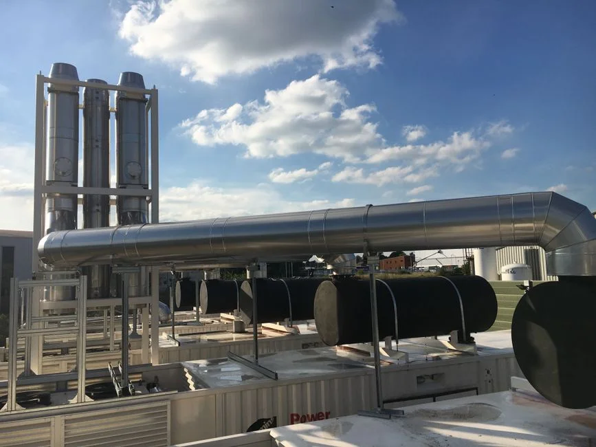
- Characterize makeup water and target COC. Pull seasonal TDS, hardness, silica, and alkalinity on the Fukuoka supply; these set the CTBD envelope and the RO recovery ceiling (Ecologix; Genesis Water Technologies). Without this, every downstream number is a guess.
- Install side-stream filtration on the cooling loop. Self-cleaning 10–25 micron filters at 1–5% of circulation flow, dropping suspended solids to protect downstream membranes (Genesis Water Technologies). This is the cheapest insurance against membrane fouling.
- Pre-filter CTBD to below 10–15 μm and dose antiscalant. Use a multi-media filter for SDI reduction followed by a PLC-controlled antiscalant and pH adjustment dosing skid. This is the precondition for stable RO operation at the upper end of the 50–85% recovery band.
- Run RO at conservative local recovery below scaling limits. Route concentrate to a controlled-precipitation reactor where silica, CaCO3, and CaSO4 are removed as dense solids on seed material, leaving a near-pure NaCl brine for further RO in a closed loop (IDE Tech). DAF for suspended-solids and metal-hydroxide removal handles the precipitated solids downstream of the reactor.
- Polish permeate and blend with fresh makeup as cooling-tower feed. Monitor Langelier Saturation Index and Ryznar Stability Index to keep makeup within the stable regime; LSI between −0.5 and +0.5 is the usual target, and staying inside that band avoids warranty loss on heat exchangers (Ecologix). An industrial RO system for cooling-tower blowdown reuse sized to actual blowdown flow delivers the permeate.
- Decide concentrate fate. Either route to MVC for high-purity distillate and a small brine volume, or send to sewer subject to Fukuoka City limits on TDS and temperature. A ZLD plant technology and buyer's guide for 2026 is worth reading if the sewer route is closed. Climate analogues are also informative: a high-TDS makeup blowdown treatment in a hot, water-stressed grid and a tropical, high-utilization hyperscaler blowdown treatment deal with similar reuse-versus-discharge tradeoffs, while a cold-climate hyperscaler blowdown treatment guide shows the other end of the seasonal envelope.
Frequently Asked Questions
What cycles of concentration should a Fukuoka AI data center target on its cooling tower?
Start at COC 4–6, the band where blowdown volume and chemistry stay in a manageable range, and confirm against the Fukuoka makeup-water silica and calcium numbers (Genesis Water Technologies). Above COC 6 the CTBD TDS climbs into the upper end of the 1,200–6,000 mg/L range, and the scaling risk on the membranes has to be designed around, not just chemically suppressed.
Which treatment unit operation should be specified first — UF, RO, or MVC?
Specify side-stream filtration on the cooling loop and UF ahead of the membranes first; without those two, the RO fouls inside months (Genesis Water Technologies). RO is the core capex item, and MVC is added only if concentrate disposal is constrained. A Fukuoka engineer should hold MVC in reserve until the Fukuoka City sewer TDS and temperature acceptance numbers are confirmed.
How much should a Fukuoka hyperscaler budget for a CTBD treatment train, and what cost inputs should be requested from bidders?
For a 50,000 GPD RO unit treating blowdown, the installed capital range is $250,000–$500,000 with opex of $1.50–$3.00 per 1,000 gallons (Genesis Water Technologies). A full ZLD train adds $3–8 million capex and $5–$15 per 1,000 gallons opex on top. The input a buyer must request from a Japanese EPC is a yen-denominated, site-specific quote that includes the Fukuoka discharge-fee schedule, the cost of makeup water, and the avoided freshwater volume — U.S. dollar benchmarks do not transfer directly.
What is the single biggest compliance risk when specifying blowdown treatment for a Fukuoka site?
The biggest risk is specifying a reuse train before confirming Fukuoka City sewerage acceptance for the projected CTBD TDS and temperature, because that single answer flips the design between reuse-as-makeup and ZLD (Ecologix). On the supplier-selection side, the check is to confirm the EPC has delivered a Japanese hyperscaler site before — a vendor with only U.S. NPDES references will not have the Water Pollution Control Act and Fukuoka City ordinance working knowledge needed for permit filing, and that gap shows up late.