How Regulators Define Secondary Treatment
The U.S. EPA sets the federal minimum technology-based standard for publicly owned treatment works (POTWs) under 40 CFR Part 133, and operators quote that regulation verbatim in design basis documents because it is the legal floor, not a target. The standard requires a minimum 85% removal of both five-day biochemical oxygen demand (BOD5) and total suspended solids (TSS), with 30-day average effluent concentrations of 30 mg/L for each parameter and 7-day average concentrations of 45 mg/L for each, according to the EPA's Secondary Treatment Standards page. The same regulation sets a pH window of 6 to 9, which matters in industrial pretreatment because discharge outside that band forces pH correction upstream of biology. The rule also allows case-by-case equivalent-to-secondary standards for trickling filters and waste stabilization ponds, and a buyer comparing a low-energy alternative to activated sludge should expect that review path, as the EPA confirms.
What Is Actually Left After Primary Treatment
Primary treatment removes settleable and floating solids by sedimentation and skimming, but the stream leaving the primary clarifier still carries dissolved organic matter, colloidal solids, and nutrients that physical settling cannot reach. Secondary treatment is the biological core that finishes that job: microorganisms oxidize dissolved organics, measured as BOD, and convert nonsettleable solids into a settleable biomass that a downstream clarifier or membrane can capture, as described in the International Journal of Science and Research review of secondary treatment mechanisms. A separation step is mandatory after the biology because the microorganisms themselves are suspended in the mixed liquor, and without clarification or membrane retention the effluent would carry a high TSS load. The word "biological" describes a family of configurations, and the differences between them come down to how oxygen is delivered, how the biomass is retained, and how the treated water is separated from the biomass.
The Main Secondary Treatment Process Options
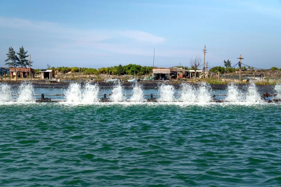
Activated sludge is the most common configuration: mixed liquor is aerated in a basin, then separated in a clarifier, and waste activated sludge yield falls as sludge age increases because more biomass is consumed through endogenous respiration. Trickling filters pass wastewater over fixed media supporting an attached biofilm; they use less energy than activated sludge but require a larger footprint and are more sensitive to temperature swings. A sequencing batch reactor (SBR) cycles a single tank through fill, react, settle, and decant, which removes the need for a separate clarifier and gives operators a flexible tool for variable influent. Moving bed biofilm reactor (MBBR) and integrated fixed-film activated sludge (IFAS) configurations suspend plastic carriers in the aeration basin so attached and suspended biomass work in parallel, raising the treatable load without enlarging the tank. A membrane bioreactor (MBR) couples activated sludge with submerged membrane filtration, delivering a high-quality secondary effluent in a smaller footprint; a packaged MBR membrane bioreactor wastewater treatment system is the modern expression of that configuration, and the flat-sheet MBR flat sheet membrane module is the replaceable element inside it. The 2026 perspective in Water Reuse on next-generation secondary treatment for potable reuse adds three more options to the shortlist upstream of advanced water purification facilities: the membrane biofilm reactor (MBfR), the Modified Ludzack-Ettinger MBR (MLE-MBR), and the anaerobic MBR (AnMBR). That review notes that MLE-MBR adds nitrogen removal but carries a significantly greater energy demand from aeration and mixed-liquor return pumping, while AnMBR offers the possibility of net energy-positive operation but does not remove nitrogen, limiting its compatibility where total nitrogen is regulated. For a buyer evaluating a small-footprint packaged plant, an underground package sewage treatment plant using one of these configurations is the typical form factor.
| Process | Growth mode | Separation | Footprint | Energy profile | Best-fit scenario |
|---|---|---|---|---|---|
| Activated sludge | Suspended | Clarifier | Moderate | High (aeration-dominated) | Steady municipal or industrial influent |
| Trickling filter | Attached (fixed media) | Clarifier | Large | Low | Low-energy sites with land available |
| SBR | Suspended (batch) | Built-in decant | Moderate | Moderate | Variable flow, small sites |
| MBBR / IFAS | Attached + suspended | Clarifier | Compact for the load | Moderate | Hydraulic or organic shock loads |
| MBR | Suspended + membrane-retained | Membrane | Small | Higher (membranes + aeration) | Reuse-grade effluent in a tight footprint |
| MLE-MBR | Suspended + membrane, with anoxic zone | Membrane | Small | Significantly higher than MBR | Nitrogen-sensitive discharge or reuse |
| AnMBR | Suspended + membrane, anaerobic | Membrane | Small | Potentially net energy-positive | High-strength industrial, no nitrogen limit |
Secondary Treatment Process Comparison
The trade-off that drives most process selection is footprint versus energy. Activated sludge and MBR dominate industrial and municipal use today, while SBR and MBBR/IFAS are the common answer where influent varies or footprint is constrained. MBR effluent quality is high enough to feed directly into reverse osmosis or UV polishing for reuse, which is why it overlaps the secondary–tertiary boundary in practice. A buyer who already has a design for an MBR train can pair it with the MBR system for sewage design criteria guide; a project-specific sizing exercise is covered in the sizing a containerized MBR STP case study. For CASS-style cyclic operation, the CASS process installation and commissioning guide walks through the same comparison at a packaged scale. For high-solids or oil-and-grease upstream duty, the dissolved air flotation for industrial wastewater design reference is the relevant companion.
| Decision driver | Leading process | Why it wins |
|---|---|---|
| Steady influent, reuse target | MBR or MLE-MBR | High effluent quality, small footprint, with nitrogen removal in MLE-MBR |
| Variable or shock-loaded influent | SBR or MBBR / IFAS | Biofilm or batch operation buffers organic and hydraulic swings |
| Energy-constrained site, land available | Trickling filter or waste stabilization pond | Lower aeration energy; eligible for equivalent-to-secondary review under 40 CFR Part 133 |
| Nitrogen-sensitive discharge | MLE-MBR or separate nitrification–denitrification | Adds anoxic biology; AnMBR alone is not suitable when TN is regulated |
| High-strength industrial, energy recovery | AnMBR | Possibility of net energy-positive operation, but no nitrogen removal |
Operating Realities: Sludge, Energy, and Monitoring
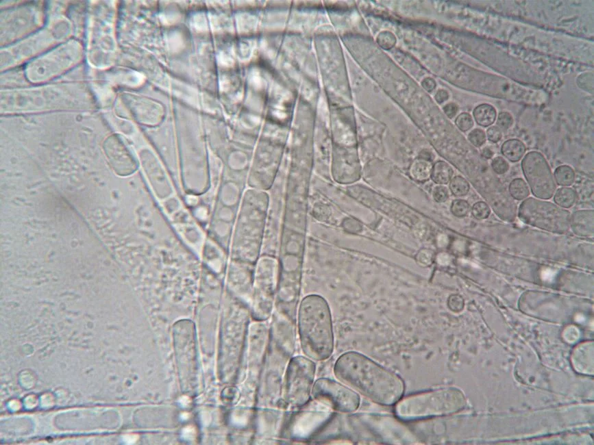
A conventional activated sludge plant produces roughly 0.4 to 0.6 kg of waste solids per kilogram of BOD removed, and that figure falls as sludge age increases because endogenous respiration consumes biomass, as summarized by the Water & Wastewater secondary treatment overview. Drinking water and wastewater systems together account for roughly 2 percent of U.S. electricity use, with the treatment plant often the largest single energy consumer a municipality operates and aeration typically half of that plant load, which makes blower and diffuser efficiency the largest single controllable cost. Without reliable data on dissolved oxygen, mixed liquor suspended solids, and sludge age, an operator is adjusting a biological process blind. An automatic chemical dosing system paired with online instrumentation is how modern plants close that loop, and the dewatering side of the operation is usually handled by a plate and frame filter press downstream of the sludge thickener. The same overview flags AI-assisted real-time control, SBR and IFAS retrofits, and resource recovery such as struvite precipitation and biogas from anaerobic digestion of waste sludge as the practices shifting secondary treatment from a disposal stage to a resource stage.
Where Secondary Treatment Stops: The Boundary With Tertiary
Secondary reliably removes BOD and TSS to within regulatory minima but does not consistently remove nitrogen, phosphorus, pathogens, heavy metals, or trace organics, and that residual fraction defines the boundary with tertiary. For industrial reuse or potable reuse (indirect or direct, IPR/DPR), the secondary effluent becomes the feed to an advanced water purification facility, typically reverse osmosis plus activated carbon plus UV or ozone, and the 2026 Water Reuse perspective explicitly evaluates MLE-MBR and AnMBR as upgraded secondary front-ends for that train. For simple river or sea discharge where the permit is the 40 CFR Part 133 baseline, secondary plus disinfection is often the complete scope, using a UV sterilizer for water treatment or a chlorine dioxide generator for the final pathogen barrier, with a reverse osmosis (RO) water purification train added only when salts or trace contaminants must come down further. This is the decision point at which a supplier conversation begins: tertiary polishing is necessary when nutrients, pathogens, salts, or trace contaminants must be reduced beyond what biology can deliver.
How to Choose the Right Secondary Treatment Configuration
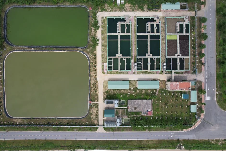
Three filters separate a defensible specification from a guess: influent variability, footprint constraint, and effluent target. Steady municipal or food-and-beverage influent with reuse goals points to MBR as the default modern answer, because it balances footprint and effluent quality. Variable industrial influent with limited footprint points to SBR or MBBR/IFAS, because the biofilm component or the batch cycle buffers hydraulic and organic shocks. An energy-constrained site with low land cost and modest effluent ambition can use a trickling filter or waste stabilization pond, both eligible for equivalent-to-secondary standards under 40 CFR Part 133 on a case-by-case basis. A nitrogen-sensitive discharge, typically when total nitrogen limits fall below 10 mg/L, calls for MLE-MBR or a separate nitrification–denitrification stage; AnMBR alone is the wrong tool where total nitrogen is regulated. The right shortlist is the one a process engineer can defend with influent data, a site footprint, and a permit number.
Frequently Asked Questions
What does secondary treatment actually remove from wastewater?
Secondary treatment removes dissolved and nonsettleable organic matter measured as BOD, along with most of the TSS that escapes primary sedimentation, by converting those fractions into settleable biomass that is then separated. It does not consistently remove nutrients, pathogens, heavy metals, or trace organics, and the residual fraction is what drives the decision to add tertiary or advanced treatment downstream.
What effluent numbers does a secondary system have to hit?
Under 40 CFR Part 133, the federal minimum is 85% removal of both BOD5 and TSS, a 30-day average effluent concentration of 30 mg/L for each parameter, and a 7-day average of 45 mg/L for each parameter, with pH held between 6 and 9. These are regulatory floors; many permits require tighter limits, and reuse applications typically require a downstream RO and UV or AOP train.
What budget range should a buyer plan for a secondary wastewater treatment system?
The supplied research does not quote a system price, so the right next step is to request a supplier quotation built on four inputs: design flow (m³/d), influent BOD and TSS, target effluent quality, and the available footprint. Bring those four numbers to every supplier so that quotations can be compared on the same basis, and ask each bidder to state the assumed sludge yield and aeration duty so the lifecycle cost is visible.
What should a buyer have ready before sizing or selecting a secondary treatment supplier?
A defensible selection starts with a representative influent characterisation (flow, BOD, TSS, ammonia, temperature, pH), the discharge or reuse permit limits, a site plan with available footprint and headroom, the utility budget for aeration and sludge handling, and any pretreatment steps already in place. Ask each supplier to map their proposed process against those inputs in writing, and to identify which of the 40 CFR Part 133 equivalent-