
Why Clarifier Selection Sets the Ceiling for the Whole Plant
A mis-sized clarifier collapses the operating window of every downstream unit. When gravity settling fails to produce a clean overflow and a dense underflow, aeration, filtration, and disinfection all lose their stable influent envelope, and the plant runs on alarms rather than by design (wxwatertech.com, 2026). Two hydraulic conditions govern whether a tank does its job: the particle settling velocity must consistently exceed the upward liquid velocity created by the surface overflow rate, and when those numbers invert during a peak wet-weather surge, solids carry over the weir into the effluent (wxwatertech.com, 2026).
Selection logic must be stage-specific because Type I discrete-particle settling dominates in primary clarifiers, while Type III zone settling — where biological floc blankets form — is typical in secondary clarifiers; confusing the two leads directly to mis-specification (wxwatertech.com, 2026). A correctly sized unit delivers four outputs: a clean overflow over the weirs, a dense underflow for downstream solids handling, a stable sludge blanket held inside the clarification zone, and an effluent typically below 30 mg/L BOD and TSS subject to permit (wxwatertech.com, 2026).
Primary Clarifier Design Criteria: SOR, Detention, and Sludge Blanket
Surface overflow rate is the primary sizing lever for first-stage sedimentation, and the published design envelope is consistent across the standard references. Qasim recommends 30–50 m³/m²·day at average flow, Metcalf & Eddy specifies 32–48 m³/m²·day at average flow and 80–120 m³/m²·day at peak hourly flow, and Ten State Standards caps the design at 40 m³/m²·day average and 60 m³/m²·day peak (Voutchkov, 2017). Hydraulic detention time of 1.5–2.5 hours at average flow per Metcalf & Eddy — or 1.0–2.0 hours per Qasim — controls whether the sludge blanket stays aerobic and pumpable; below that, the blanket turns septic and releases gas that disturbs the settling column (Voutchkov, 2017). The conventional design envelope therefore runs 33–49 m³/m²·day (800–1,200 gal/ft²·day), and ballasted flocculation raises the design SOR to at least 160 m³/m²·day (4,000 gal/ft²·day), a 3–5x capacity unlock in the same footprint (Voutchkov, 2017). Effluent weir loading must stay below 190 m³/day per metre of weir (5,000 gpd/ft) to avoid localized high-velocity carryover over the launder (Voutchkov, 2017). Performance targets for a well-designed primary clarifier are 50–65% TSS removal, 25–35% BOD removal, and 5–10% nitrogen and phosphorus removal (Voutchkov, 2017). The optimum primary sludge blanket runs 1–3 ft deep at 3–5% solids; continuous or very frequent withdrawal prevents septicity and gas-driven disturbance of the blanket (Voutchkov, 2017; fehrgraham.com, 2026).
| Design Source | SOR — Average Flow (m³/m²·day) | SOR — Peak Hourly Flow (m³/m²·day) | Hydraulic Detention Time (hrs) |
|---|---|---|---|
| Metcalf & Eddy | 32–48 | 80–120 | 1.5–2.5 |
| Ten State Standards | ≤ 40 | ≤ 60 | — |
| Qasim | 30–50 | 40 typical avg / 70–130 peak | 1.0–2.0 |
| Ballasted flocculation (Voutchkov) | ≥ 160 | — | — |
Industrial streams break the municipal envelope. Plants that accept hauled septage, food waste co-digestion feed, or grit-bearing flows carry more settleable solids than a domestic sewer, so the SOR must be checked against site settleability data rather than a textbook average (lakeside-equipment.com, 2026). For high-FOG food-processing streams, tightening the SOR and installing an upstream dissolved air flotation unit is the standard way to strip floatables before they overload the primary blanket; pairing the clarifier with a HydropureWater DAF system on the FOG stream and a HydropureWater automatic chemical dosing system for coagulant feed is the typical retrofit pattern.
Secondary Clarifier Design Criteria: SOR, SLR, and Sludge Blanket Stability
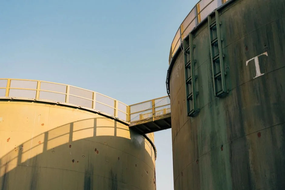
The secondary clarifier has two jobs: clarify the biologically treated wastewater and thicken the sludge for return (RAS) or wasting (WAS). Two design criteria must be checked, and they catch different failures — the surface overflow rate catches the clarifier function, and the solids loading rate (SLR) catches the thickener function (Voutchkov, 2017). Biological floc is fragile, so secondary SOR tightens to 20–30 m³/m²·day — deeper into the envelope than primary — because the buoyant floc settles more slowly than discrete particles (wxwatertech.com, 2026). Sidewater depth of 3.5–5 m is standard for secondary units, and SWD must rise to at least 4.3–5 m to prevent sludge-blanket washout under prolonged wet-weather flows (wxwatertech.com, 2026; fehrgraham.com, 2026). The optimum sludge blanket sits 0.3–0.9 m above the tank floor; once the blanket approaches the weirs, solids escape (wxwatertech.com, 2026). Effluent weir loading must not exceed 124 m³/day per metre of weir (10,000 gpd/ft) to keep localized carryover under control (Voutchkov, 2017).
| Design Source | Secondary SOR (m³/m²·day) | Secondary SLR (kg/m²·hr) | SWD (m) | Weir Loading Limit (m³/day·m) |
|---|---|---|---|---|
| Metcalf & Eddy (after air activated sludge, excl. extended aeration) | 16–28 | 3.9–5.9 | 3.5–5.0 | ≤ 124 |
| Metcalf & Eddy (after extended aeration) | 8–16 | 2.0–4.9 | 3.5–5.0 | ≤ 124 |
| Metcalf & Eddy (after trickling filtration) | 16–28 | 3.9–5.9 | 3.5–5.0 | ≤ 124 |
| Wet-weather design rule (Fehr-Graham) | — | — | ≥ 4.3–5.0 | — |
For older secondary tanks that struggle with rising sludge or pin floc, a flocculating center feed well is the upgrade path: radius extended to 20–50% of the tank radius, detention of 20–30 minutes, and well depth at 40–50% of the tank depth (Voutchkov, 2017). Many modern plants tie blanket-level monitors to RAS pump speed to keep the interface stable, and downstream polishing via an HydropureWater MBR system or a HydropureWater high-efficiency lamella clarifier catches the carryover events that even a well-sized secondary cannot fully prevent under sustained hydraulic surge.
Geometry Decision: Circular, Rectangular, or Lamella
For plant-scale applications, three physical geometries cover the majority of installations. The right shape depends less on tradition than on available footprint, sludge characteristics, and the cost of civil construction (wxwatertech.com, 2026). Circular clarifiers scale from 3 m up to over 100 m diameter, with sidewater depth of 2.5–5 m, and dominate large municipal secondary duty because the rotating scraper is mechanically simple and the sludge collection path is short (Voutchkov, 2017). Rectangular clarifiers with L:W from 3:1 to 15:1, widths of 2–6 m, depths of 2–6 m, and a minimum 3 m length, win on shared-wall civil cost and are common where multiple parallel units are needed (Voutchkov, 2017; wxwatertech.com, 2026). Lamella / inclined-plate settlers pack 45–60° plates at 40–120 mm spacing into roughly 2 m vertical depth, multiplying effective settling area to give a footprint roughly one-tenth of an equivalent conventional clarifier (Voutchkov, 2017; wxwatertech.com, 2026).
| Geometry | Typical Dimensions | Footprint vs. Conventional | Solids Capture Strength | Key Weakness |
|---|---|---|---|---|
| Circular (center feed) | 3–60+ m Ø; SWD 2.5–5 m | Baseline (1x) | Good for high-capacity secondary | Short-circuiting risk if inlet baffle undersized |
| Circular (peripheral feed, Spiraflo/Spiravac) | Outer ring + skirt + central hopper | Baseline (1x) | 2x–4x better than center feed on solids capture (Lakeside) | More complex inlet hydraulics |
| Rectangular | L:W 3:1–15:1; width 2–6 m; depth 2–6 m; min length 3 m | Lower via shared walls | Higher acceptable weir loading; better sludge thickening | Chain-and-flight wear; broken flight stops unit |
| Lamella / inclined plate | Plates 45–60°, 40–120 mm spacing, ~2 m vertical depth | ~0.1x | SOR equivalent to much larger conventional tank | Floc-quality sensitive; periodic acid cleaning required |
Center-feed wells on circular units are sized at 15–25% of tank diameter, extend 30–75% of SWD, and are designed for an average downflow velocity of 10–13 mm/s and a maximum of 25–30 mm/s (Voutchkov, 2017). Peripheral-feed designs like the Spiraflo and Spiravac are reported by Lakeside Equipment to perform 2x–4x better than center-feed on solids capture, at the cost of more complex inlet hydraulics (lakeside-equipment.com, 2026). The geometry decision therefore comes down to flow volume, available footprint, and what the solids will do inside the tank — short-circuiting risk in circular units, chain-and-flight wear risk in rectangular units, and floc-quality sensitivity in lamella units (wxwatertech.com, 2026). For plants with a tight industrial footprint and a heavy hydroxide or FOG load, a HydropureWater high-efficiency lamella clarifier is often the geometry that lets the site hit its SOR without expanding the civil envelope.
Wet-Weather and Peak-Flow Resilience
Wet weather drives grit washout into primary clarifiers and dilutes secondary influent; the sludge blanket shifts and transient flows can diminish performance on both stages (fehrgraham.com, 2026). The wet-weather design rule for new builds and high-solids retrofits is to raise sidewater depth to at least 4.3–5 m, which absorbs the surge without blanket washout (fehrgraham.com, 2026). Ballasted flocculation — coagulant plus micro-sand plus inclined plates — is the retrofit lever that lets an existing footprint accept the wet-weather load (fehrgraham.com, 2026; Voutchkov, 2017). Coagulant and polymer ahead of the clarifier bind fine colloids into flocs that settle 2–5x faster than untreated solids, which is the lever to pull when peak flow is the constraint and tank size is fixed (wxwatertech.com, 2026). A high-solids separation facility can also be operated as a primary clarifier during wet weather, and chemically enhanced primary treatment is a feasible alternative to increasing the biological treatment capacity when the surge is sustained (fehrgraham.com, 2026). For more on the trade-off between flotation and settling under heavy industrial loads, see the comparison on DAF vs clarifier for mining and metals wastewater.
Pre-Specification Checklist: Turning Criteria Into a Sized Selection
Before locking the geometry and the SOR/SLR envelope, assemble the site data that drives every parameter above. The minimum input set is average and peak hourly flow, influent TSS/BOD/FOG, temperature, settleable-solids fraction, available footprint, civil cost envelope, and the target effluent BOD/TSS (wxwatertech.com, 2026). Cross-check the four common specification misses that show up in operational audits: under-sized SWD, over-aggressive SOR, ignored peak wet-weather flows, and poorly sized upstream flocculation (wxwatertech.com, 2026). Build the maintenance envelope into the spec rather than leaving it for after award: torque-sensing drive, chain tension monitoring, weir algae control, and sludge-pump redundancy are all part of the equipment list, not an afterthought (wxwatertech.com, 2026). For pretreatment upstream of the clarifier, the chemistry story is covered in the primer on how DAF systems work in industrial pre-treatment, which is the typical reference when coagulant and polymer selection is being justified to procurement.
Frequently Asked Questions
What SOR should I use for a primary clarifier handling food-processing wastewater with high FOG?
FOG is a settleable solid, but it floats rather than sinks, and emulsified FOG acts as a colloid that resists gravity settling. The 30–50 m³/m²·day envelope from the standard references is set for municipal-style settleables, so a high-FOG stream needs to be verified against site settleability data rather than the textbook average (lakeside-equipment.com, 2026). The actionable check is to run jar tests on the actual food-processing wastewater with and without coagulant, measure the settleable-solids fraction, and tighten the SOR proportionally if the fraction is high. The standard mitigation upstream of the primary clarifier is a DAF unit for FOG strip and a coagulant dosing system, which together let the primary run at the published SOR instead of derated for FOG overload (Voutchkov, 2017).
When does a lamella clarifier replace a circular or rectangular unit?
Lamella / inclined-plate settlers replace a conventional circular or rectangular unit when the available footprint is the binding constraint, when the flow is relatively low to moderate, and when the upstream coagulant and flocculation step can deliver a stable, well-formed floc (Voutchkov, 2017; wxwatertech.com, 2026). They are common in industrial metal hydroxide precipitation, cooling tower blowdown, and as retrofit capacity boosters inside existing conventional basins (wxwatertech.com, 2026). The actionable check before specifying is to confirm a stable floc via jar testing and to budget for periodic acid cleaning of the plate packs, which is the maintenance penalty for the footprint advantage.
How do I know if I need ballasted flocculation vs a larger conventional tank?
Ballasted flocculation is the right answer when the design SOR is forced above the conventional 33–49 m³/m²·day envelope by peak wet-weather flow, hauled-waste loads, or a footprint constraint that a larger tank cannot solve (Voutchkov, 2017; fehrgraham.com, 2026). The 3–5x SOR uplift to at least 160 m³/m²·day is the technical lever, and the cost justification is civil-work avoidance. The actionable check is to obtain a site-specific SOR target from the design flow plus the wet-weather peak, then compare the cost of an enlarged conventional basin against the ballasted system capex plus the ongoing micro-sand and coagulant consumables.
What sidewater depth protects against wet-weather sludge blanket washout?
The wet-weather design rule from operational data is a sidewater depth of at least 4.3–5 m for new builds and high-solids retrofits, which is deeper than the 3.5–5 m standard secondary envelope and prevents the sludge blanket from rising into the weirs during sustained hydraulic surge (fehrgraham.com, 2026). The actionable check for procurement is to confirm that the bidder's SWD meets the lower bound of 4.3 m under the peak hourly flow condition, not just the average. Where a new tank at that depth is not feasible, the alternative is ballasted flocculation or a high-solids separation facility operated as a primary during wet weather (fehrgraham.com, 2026).
How is solids loading rate (SLR) different from SOR, and which one drives secondary clarifier sizing?
SOR measures hydraulic loading on the clarifier surface in m³/m²·day, and SLR measures solids loading on the same surface in kg/m²·hr — the first catches the clarification function, the second catches the thickening and storage function (Voutchkov, 2017). The actionable check is to size the tank to the larger of the two required surface areas, because a secondary clarifier that passes the SOR test can still fail on sludge thickening if the SLR is over the limit. For typical air-activated-sludge duty the published SLR envelope is 3.9–5.9 kg/m²·hr; for extended-aeration duty it tightens to 2.0–4.9 kg/m²·hr (Voutchkov, 2017).