What an Electrocoagulation System Actually Has to Do
An electrocoagulation system design begins with matching the target contaminant to a sacrificial electrode — iron or aluminum — and then sizing the cell around current density, electrode spacing, hydraulic retention time, and pH. Monopolar or bipolar electrode connections and plate, tubular, or airlift reactor geometries are selected based on wastewater conductivity, flow rate, and the downstream separation step. The supplied research confirms electrocoagulation has been demonstrated for arsenic, copper, chromium, nickel, lead, cadmium, fluoride, dyes, oils, and food-industry streams, and that electrode distance and treatment time are the primary kinetic levers. The principal design constraints are energy consumption, regular electrode replacement, and sludge handling downstream.
For a process engineer, the design problem is not "what is electrocoagulation" but "what does the reactor have to do while contaminants are being removed." Three parallel processes run on every electrode pair: sacrificial metal ions dissolve into solution, hydrogen gas evolves at the cathode and oxygen at the anode, and water heats as current passes through a low-conductivity medium. The S2 review (Environmental Science and Pollution Research) and the S3 commercial glossary both frame these as ongoing design constraints rather than side effects. That framing matters because the cell, the power supply, and the downstream tank must be sized for all three processes simultaneously, not just for contaminant removal. The design must also accept that electrodes will be consumed and must be replaced on a schedule, which dictates cell geometry, lifting provisions, and electrical connection design. An automatic chemical dosing system is often paired with the cell for pH correction and conductivity adjustment, because raw feed rarely sits inside the EC operating window on its own.
Feedwater Characterization: The Inputs the Design Cannot Skip
Before any sizing math, the engineer needs a feed characterization. The S2 review and the S3 glossary both name the same controlling variables: contaminant identity and concentration, pH, conductivity, total suspended solids, temperature, and flow rate. Without these, current density and retention time cannot be selected, and the operating cost model cannot be built. Treat this characterization as a gate: if the plant cannot supply values for every row in the table below, the design is not ready to move to cell sizing.
The S2 review documents an unusually broad track record for EC. Balasubramanian et al. 2009 demonstrated arsenic removal; Akbal and Camc 2011 removed copper, chromium, and nickel from metal-plating wastewater; Bazrafshan et al. 2008 addressed hexavalent chromium with iron and aluminum electrodes; Ghosh et al. 2008 removed fluoride using monopolar and bipolar connections; Aoudj et al. 2010 worked on textile dyes; Asselin et al. 2008a treated oily bilgewater. That breadth does not mean EC is universal. Canizares et al. 2009, also cited in the S2 review, identifies pH as the parameter that separates EC from chemical coagulation — outside the metal-hydroxide precipitation window, removal collapses and passivation risk rises. Streams with very low conductivity are energy-inefficient without electrolyte addition, and very high oil loads need pre-separation before the cell. A multi-media filtration step upstream can be used to drop TSS to a level the cell can tolerate.
| Input | Why it matters for EC design | Source |
|---|---|---|
| Contaminant identity and concentration | Selects electrode material, sets target removal efficiency | S2 review; S3 glossary |
| pH | Determines whether metal-hydroxide flocs form at all | Canizares et al. 2009 (S2) |
| Conductivity | Drives cell voltage and energy consumption; very low values need NaCl or similar electrolyte | S2 review; S3 glossary |
| Total suspended solids | High TSS fouls electrodes and reduces current efficiency | S3 glossary |
| Temperature | Affects reaction kinetics and gas evolution rate | S2 review |
| Flow rate (continuous) or batch volume | Sets hydraulic retention time and electrode count | S2 review |
Choosing the Sacrificial Electrode: Iron vs Aluminum
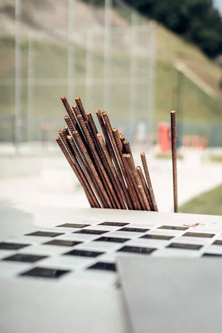
Electrode material is the single choice that drives every downstream parameter. The S2 review and the S3 glossary both state that EC electrodes are usually iron or aluminum, and that the dissolved metal ions react with contaminants to form insoluble compounds. The research literature is not split evenly between the two — each material has a documented niche. Iron electrodes are the dominant choice when the target is arsenic, trivalent chromium, or a broad heavy-metal mix. Al Aji et al. 2012 worked with monopolar iron electrodes for heavy-metal-bearing model wastewater, and Golder et al. 2006 and 2007 specifically removed Cr3+ with iron, including a comparison of bipolar and monopolar configurations. Aluminum electrodes dominate where hydroxide-floc generation is the primary goal: Bayramoglu et al. 2007 used aluminum for textile dye removal, and the S5 Europe PMC study optimized an aluminum-electrode process for household wastewater.
Barrera-Díaz et al. 2008, cited in the S2 review, ran a direct iron-versus-aluminum comparison in hydrogen-peroxide-assisted EC, which is a useful reminder that the choice is rarely binary once a real waste is tested. Hybrid and mixed-metal stacks appear throughout the literature. The S3 glossary notes that sludge chemistry tracks the electrode material: iron sludge tends to be denser and is often magnetic, which affects pump and conveyor selection downstream; aluminum sludge is lighter and more gelatinous, which favors different dewatering geometries. For most metal-finishing applications, that downstream mismatch is what decides the electrode. A plate and frame filter press handles iron-rich sludge well; aluminum floc often benefits from a flotation step before mechanical dewatering.
| Material | Typical target contaminants | Documented reference | Sludge characteristic |
|---|---|---|---|
| Iron (Fe) | Arsenic, Cr3+, mixed heavy metals | Al Aji et al. 2012; Golder et al. 2006, 2007 (S2) | Denser, often magnetic |
| Aluminum (Al) | Dyes, fluoride, organic matter, domestic wastewater | Bayramoglu et al. 2007; S5 Europe PMC | Lighter, more gelatinous |
| Hybrid Fe/Al | Streams where iron and aluminum each remove different fractions | Barrera-Díaz et al. 2008 (S2) | Mixed; test on the actual feed |
Reactor Geometry and Electrical Configuration
Reactor geometry and wiring are two decisions that the academic record and the S3 glossary both discuss, but neither turns into a usable decision framework. The S2 review documents both monopolar and bipolar connections across multiple studies: Al Aji et al. 2012 used monopolar iron electrodes; Asselin et al. 2008b and 2008c directly compared monopolar and bipolar cells for slaughterhouse wastewater; Golder et al. 2007 ran bipolar and monopolar configurations for trivalent chromium; Ghosh et al. 2008 used both for fluoride removal. The wiring choice is fundamentally a plant-electrical question. Monopolar series strings need higher DC voltage but allow individual electrode removal; bipolar stacks operate at lower voltage because each interior electrode is energized through the water column, but every plate must remain in place for the circuit to function.
Plate cells are the workhorse for batch and moderate-flow continuous duty and dominate commercial EC skids. Tubular and external-loop airlift reactors are documented by Essadki et al. 2008 and Hansen et al. 2008 in the S2 review, with Hansen et al. specifically targeting arsenic removal in an airlift geometry. The airlift choice pays off when gas handling and mixing matter more than raw throughput — for example, when the cell must strip a volatile contaminant or when floc breakage in a high-shear plate cell is a known problem. Electrode spacing is one of the two most-optimized design variables in the S5 Europe PMC study: closer spacing raises current per unit area but increases short-circuit risk and the maintenance difficulty of plate cleaning. The plate-versus-tubular decision is driven less by the contaminant than by available floor space, the need to handle gas, and the maintenance philosophy. The plate, tubular, and airlift cells all appear in the literature with documented performance; the engineer's job is to match the geometry to the plant's operational constraints rather than to the contaminant alone.
| Configuration | Documented application | Strength | Limitation |
|---|---|---|---|
| Monopolar plate cell | Heavy-metal removal (Al Aji et al. 2012); slaughterhouse (Asselin et al. 2008b) | Easy electrode replacement, flexible series/parallel | Higher DC voltage required |
| Bipolar plate stack | Cr3+ removal (Golder et al. 2007); fluoride (Ghosh et al. 2008) | Lower voltage per plate, compact stack | All plates must remain in place |
| External-loop airlift | Textile dye (Essadki et al. 2008); arsenic (Hansen et al. 2008) | Good gas–liquid mixing, handles H2 safely | Higher footprint, pump energy |
| Tubular cell | Documented in S2 review; small-footprint continuous duty | Compact, suited to pressurized flow | Limited plate area per unit volume |
Key Process Parameters the Designer Must Set
Every EC reactor specification reduces to a small set of parameters that the designer must set before a vendor can quote hardware. Current density, expressed in A/m² of electrode area, sets the metal dissolution rate and therefore the coagulant dose; the S2 review and the S3 glossary both name it as the primary control handle. Treatment time, or hydraulic retention time for continuous reactors, is the second major kinetic variable, and the S5 Europe PMC study explicitly identified electrode distance and treatment time as the two factors driving removal in an aluminum-electrode system. pH is a separate design input rather than a free outcome: Canizares et al. 2009, cited in the S2 review, demonstrated that pH is the parameter that determines whether coagulation or electrocoagulation is the right tool, and outside the metal-hydroxide precipitation window the flocs simply do not form.
Conductivity drives the cell's electrical efficiency. The S3 glossary names current and conductivity as the two primary efficiency drivers, and the practical implication is that low-conductivity streams need added electrolyte — sodium chloride is the most common choice — to keep the cell from becoming an electric heater. Electrode life is a recurring OPEX line item, not a maintenance surprise; the S3 glossary is explicit that electrodes degrade with use and require regular replacement, and the engineer must plan replacement as a scheduled event with spare electrode stock and cell access provisions. The table below lists the parameters the designer must set; the values themselves must come from jar tests and pilot work on the actual feed, because the supplied research does not provide universal ranges that apply across contaminants.
| Parameter | What it controls | Source of value |
|---|---|---|
| Current density (A/m²) | Metal dissolution rate; coagulant dose | Jar test + pilot on actual feed (S2, S3) |
| Electrode spacing | Cell voltage, current distribution, short-circuit risk | S5 Europe PMC optimization |
| Hydraulic retention time | Reaction completion; tank volume | S5 Europe PMC; kinetic study on actual feed |
| Operating pH window | Floc formation, metal-hydroxide solubility | Canizares et al. 2009 (S2) |
| Minimum feed conductivity | Cell energy efficiency; electrolyte dosing need | S3 glossary; pilot measurement |
| Electrode replacement interval | OPEX scheduling; spare parts inventory | S3 glossary; pilot mass-loss data |
| Energy consumption (kWh/m³) | Operating cost; power-supply sizing | S3 glossary; pilot kWh meter |
An automatic chemical dosing system handles pH adjustment and electrolyte makeup so the cell sees a stable feed, which is what makes the parameters above achievable in practice rather than theoretical.
Integrating EC with Downstream Separation
EC only does half the job. The metal-hydroxide flocs that form in the cell have to be removed, and that downstream step is part of the design envelope, not an afterthought. The S3 glossary states explicitly that the flocs are larger and heavier than the original contaminants and are removed by settling or filtration. The S2 review supports the same conclusion across multiple feed types. The choice of separation device is driven by floc density and by the waste stream's oil and grease content. For oily bilgewater and slaughterhouse or restaurant wastewater — documented in Asselin et al. 2008a, 2008b, 2008c, and Chen et al. 2008 — a dissolved air flotation (DAF) system is the standard pairing because the flocs are buoyant and the entrained H2 micro-bubbles assist flotation. For metal-plating streams where iron flocs are denser, gravity settling in a high-efficiency lamella clarifier followed by mechanical dewatering on a plate and frame filter press is the more common train.
The S3 glossary also notes that EC sludge is typically less voluminous than chemical-coagulation sludge, but the sludge line still has to be designed. The engineer must size a sludge thickener, a sludge holding tank, and a dewatering device; the filter press, DAF, and clarifier links above are the unit operations that close the loop. The integration is also a controls integration: the cell's pH probe and the clarifier's sludge-bed probe share a PLC, and the sludge pump runs on a timer or a consistency signal rather than continuously. Without that integration, the system either over-produces dilute sludge or under-produces and lets floc carry over into the effluent. For an overview of how EC fits into a broader organic-removal train, the chemical wastewater COD removal guide walks through the same separation-decision logic in a different context.
Controls, Instrumentation, and Passivation Management

The controls and maintenance side of EC is where academic and commercial sources tend to thin out, and it is also where projects fail after installation. The S3 glossary names the required instrumentation: pH, conductivity, temperature, and applied current and voltage monitoring, all of which govern removal efficiency. Industrial EC skids are typically controlled by a PLC that holds current setpoint, monitors pH and conductivity, and triggers electrolyte and acid or caustic dosing through an automatic chemical dosing system. Polarity reversal is a standard control loop; the S3 glossary mentions alternating-current EC, and the S2 review cites Eyvaz et al. 2009 on AC-EC for dye removal. Periodic DC polarity reversal is the more common industrial approach because it does not require an AC supply and it disrupts the oxide film that builds on the cathode during extended DC operation.
Passivation is the dominant long-term performance problem. The S3 glossary calls electrode degradation and the resulting efficiency loss a core limitation. The S2 review documents the same problem implicitly — multiple studies reported re-polishing or replacing electrodes mid-experiment to recover performance. Polarity reversal slows but does not eliminate passivation, and a scheduled acid wash or mechanical cleaning of the plates is usually part of the maintenance plan. The engineering implication is that the cell must be designed for service access: lifting fixtures, removable electrode racks, and a clear maintenance procedure for the operators. Spare electrode stock should be sized to the replacement interval, which itself must come from pilot mass-loss data on the actual feed. The PLC should also track amp-hours per electrode pair, because that is the leading indicator of when a plate is nearing end of life, not a calendar date. For a related controls-and-commissioning reference, the cavitation air flotation commissioning guide covers the same instrumentation philosophy on a flotation train.
Commissioning, Pilot Testing, and Scale-Up Checklist
Paper designs do not survive contact with real wastewater. The S5 Europe PMC study used response surface methodology to optimize an aluminum-electrode system, which is the academic community's term for running a structured set of experiments across current density, spacing, and time on the actual feed. The engineer should plan for the same thing: jar tests first to screen chemistry, then a bench- or pilot-scale EC cell with the real wastewater before a full-scale purchase order is cut. The pilot work has to vary the two factors the S5 study treated as primary — electrode distance and treatment time — and it has to monitor energy consumption per cubic meter treated, because the S3 glossary frames energy as a primary cost factor and the pilot kWh number is what the full-scale operating-cost model hangs on.
The pilot must also confirm the downstream separation step. There is no point optimizing the cell if the DAF, lamella, or filter press that follows cannot handle the actual floc. Run the pilot cell into a small DAF or a jar settling test and verify that the floc separates cleanly, that the sludge thickens to a pumpable consistency, and that the effluent meets the discharge target for the contaminants of interest. The S3 glossary confirms that EC achieves high removal efficiencies for lead, copper, nickel, and chromium, but those numbers come from the literature, not from the plant's specific feed. Document the influent and effluent concentrations for every contaminant of concern so the compliance case and the ROI calculation both have real data behind them. The table below is a working checklist for that pilot-to-procurement path.
| Stage | What to do | What to record |
|---|---|---|
| Jar tests | Screen pH, electrode material, coagulant dose | Residual contaminant, floc settling rate |
| Bench-scale EC cell | Vary current density, electrode spacing, time | Removal efficiency, kWh/m³, electrode mass loss |
| Pilot with downstream step | Run cell into DAF or lamella on real feed | Effluent quality, sludge solids, separation problems |
| Full-scale specification | Use pilot results to size plate count, current, tank volume | Vendor RFQ with documented performance basis |
| Commissioning | Verify current distribution, pH control, polarity reversal | Baseline kWh, baseline effluent quality |
Frequently Asked Questions
What is the realistic operating cost of an electrocoagulation system per cubic meter treated?
The S3 commercial glossary names energy consumption as a primary cost factor and electrode replacement as a recurring maintenance cost, but the research does not supply a universal kWh/m³ or USD/m³ figure that applies across feeds. The realistic answer is that operating cost is feed-specific: it depends on the current density the contaminant requires, the conductivity of the stream, the electrolyte dose, and the electrode replacement interval. A buyer should request a pilot kWh/m³ number on the actual wastewater and a written electrode-life estimate in operating hours or amp-hours per plate, then build the operating-cost model from those two inputs.
How do I choose between a plate cell, an airlift reactor, and a tubular cell for my application?
Plate cells are the default for batch and moderate-flow continuous duty and dominate commercial EC skids. External-loop airlift reactors, documented by Essadki et al. 2008 and Hansen et al. 2008 in the S2 review, are favored when gas handling and mixing matter — for example, in arsenic removal or dye streams where floc breakage is a problem. Tubular cells suit pressurized, compact continuous duty. The selection is driven by the plant's floor space, the need to handle H2 safely, and the maintenance philosophy more than by the contaminant. A supplier should be asked for documented case studies on a similar feed and flow rate, not just a generic data sheet, because the research does not give a universal geometry-to-contaminant mapping.
What compliance and quality documentation should I require from an EC equipment supplier before purchase?
The supplier should provide a documented performance basis on a wastewater similar in conductivity, pH, and contaminant type to the plant's actual feed, with measured removal efficiencies and kWh/m³ data. The supplier should also provide a written electrode-life estimate in operating hours or amp-hours, a list of spare parts with lead times, and a controls narrative covering pH, conductivity, current, and polarity-reversal logic. Material certificates for the electrodes, a PLC I/O list, and a P&ID are standard deliverables on industrial skids. A site visit to an installed unit of similar scale is the most useful single check, because it reveals maintenance access and real electrode-replacement frequency that brochures do not.
What are the most common reasons electrocoagulation systems underperform after installation?
Three causes appear repeatedly in the research and in the field. First, pH drifts outside the metal-hydroxide precipitation window identified by Canizares et al. 2009 in the S2 review, and removal collapses. Second, electrode passivation builds up between scheduled cleanings, and the S3 glossary calls this a core limitation; without polarity reversal and a maintenance plan, current efficiency drops. Third, the downstream separation step is undersized for the actual floc volume, which lets floc carry over into the effluent. Each of these is detectable in a well-run pilot before the full-scale unit is purchased. The S3 glossary also flags very low conductivity as an energy-efficiency trap, which can be diagnosed with a simple conductivity meter on the feed. A pre-purchase pilot that monitors pH, conductivity, current, effluent quality, and sludge solids will surface all three failure modes before they become expensive field problems. For related sizing context on the separation side, the DAF vs clarifier guide for mining and metals wastewater walks through the same pilot-first logic for the downstream train.