Why Installation and Commissioning Decide Whether a CAF Unit Performs
Cavitation air flotation (CAF) was invented in 1985 specifically to remove the air compressor, recirculation pump, and pressure saturation tank that complicate dissolved air flotation (DAF) installation (Finn, IPPTA 1995). That mechanical simplification shifts the installation risk from pipework and pressure vessels onto four procedural points: aerator rotation direction, mechanical alignment of the hollow four-pronged impeller, draft tube seal integrity, and weir leveling. Getting any of these wrong costs weeks of troubleshooting, not hours.
The commissioning target is the published removal band, not the nameplate flow. Demonstrated performance is 90-97% suspended solids removal, 95% fats-oils-grease (FOG) removal, and 40-70% BOD reduction depending on the SS/BOD relationship of the feed (Finn, IPPTA 1995; SIGMADAF, 2025). Because suspended solids typically carry 30-70% of influent BOD, a correctly commissioned CAF directly sets the load on every downstream biological stage (Finn, IPPTA 1995). The acceptance test later in this procedure is built around those numbers.
For most plant engineers reading this, the unit is arriving as a skid on a truck. The rest of this article is the procedural document to install, start, and sign off that skid against measurable criteria.
CAF Operating Parameters the Commissioning Engineer Must Know
Every step in the rest of this article is anchored to the design numbers in the table below. These figures come from the original CAF technical literature and current manufacturer datasheets and should appear on the unit nameplate and in the O&M manual (Finn, IPPTA 1995; SIGMADAF, 2025). If the nameplate disagrees with the table, the nameplate and the O&M govern.
| Parameter | Design Value | Notes for Commissioning |
|---|---|---|
| Hydraulic capacity | 3-250 m³/h | 13 standard model sizes (SIGMADAF, 2025) |
| Aerator speed | 1,700 rpm | Fixed by impeller design; verify with tachometer |
| Aerator motor | 2-3 hp (2.5 hp at 20 m³/h; 3.5 hp at 150 m³/h) | Verify overload setting matches nameplate FLA |
| Scraper / auger drive | 1/2 hp geared motor with variable speed | Sets sludge thickness and surface removal rate |
| Microbubble size | 500 Nm to 1 mm | Generated by cavitation, not compressed air |
| Floc retention (cavitation chamber) | 2-4 seconds | Sets flocculant injection point distance from inlet |
| Flotation retention (clarification chamber) | 17 minutes | Optimizes clarification and sludge thickening |
| Natural recycle | 20-25% of hydraulic flow | Driven by vacuum, not a pump |
| Construction material | AISI 304 or 316 stainless steel | 316 for corrosive or high-FOG service |
| Air source | Natural suction via draft tube | No compressor, no saturation tank |
Two numbers on this table are routinely misread at site and worth flagging now. Microbubble size is 500 nanometres to 1 millimetre — the unit is the giveaway, since a 500 mm bubble is physically impossible. And the 2-4 second retention is in the cavitation chamber at the inlet end, not the 17 minute retention in the flotation chamber downstream. Conflating the two is the most common cause of misplaced chemical injection.
Site, Foundation and Utility Preparation Before the Unit Arrives
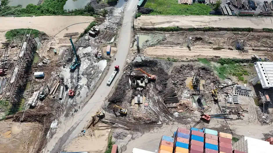
The CAF skid is rectangular, compact relative to its flow rating, and ships with integral scraper and auger drives. Civil work should be complete before delivery: a level concrete pad rated for the empty unit weight plus full water and sludge weight at design flow, with at least 600 mm clearance around the skimmer and auger drives for maintenance access (SIGMADAF, 2025). Skew the pad out of level by more than 5 mm across the weir length and the adjustable weir will not produce a uniform hydraulic head across the tank.
Three utilities must be in place at the pad edge before setting the skid:
- Three-phase power sized for the aerator motor (2-3 hp standard, scaling to 3.5 hp at 150 m³/h per Finn, IPPTA 1995) plus the 1/2 hp scraper/auger geared motor. Include a local disconnect and overload protection per the nameplate full-load amps.
- Influent feed line with pH probe, coagulant injection point, and a flocculant injection point located so the coagulant has 30-60 seconds of contact time before the flocculant meets the flow at the cavitation chamber inlet (Finn, IPPTA 1995).
- Effluent discharge line tied to the adjustable weir outlet and routed to the next treatment stage or sewer per the discharge permit.
Ancillaries the installer is responsible for, not the skid supplier, include a sludge container or transfer pump, a chemical dosing skid, and room ventilation. Because the draft tube draws ambient air by natural suction, the room must be free of corrosive or flammable vapours — a CAF installed in a confined space drawing solvent-laden air is a fire and corrosion problem waiting to happen. Position the automatic chemical dosing skid so coagulant and flocculant injection points sit at the distances above from the cavitation chamber inlet; this is the only way to hit the 2-4 second floc retention window reliably.
Mechanical and Electrical Pre-Commissioning Checklist
Run this punch list before water ever enters the tank. Every item on it has caused a multi-day startup delay on at least one of the units we have commissioned, and none of them are visible once the tank is full.
| Step | Check | Pass Criterion |
|---|---|---|
| 1. Visual and dimensional | Tank level on pad; weir plumb and adjustable; skimmer scraper blade-to-beach gap; auger flight clearance in trough | Pad level within 5 mm across weir length; scraper blades clear the beach by manufacturer-specified gap; auger turns freely by hand |
| 2. Rotating equipment | Cavitation aerator is a hollow four-pronged impeller (Finn, IPPTA 1995); rotation direction; speed | Matches nameplate arrow at 1,700 rpm; tachometer reading within ±5%; incorrect rotation destroys the vacuum and stops bubble generation |
| 3. Draft tube integrity | Tube sealed to chamber; air inlet unobstructed; no leak at flange | Soap-bubble test on seals shows no leakage; air inlet clear of debris; ambient airflow audible at the inlet when impeller spins |
| 4. Electrical | Insulation test on aerator and scraper/auger motors; phase rotation; overload settings; VSD on scraper/auger | Megger reading per motor nameplate; phase sequence matches arrow; overload set at motor FLA; VFD programmed for scraper speed range |
| 5. Instruments | Level sensor in flotation chamber; pH probe on inlet line; flowmeter on influent or recirculation line | Calibration certificates current; level sensor reads true at operating weir set-point; pH probe calibrated with two-point buffer; flowmeter zeroed on static line |
Two of these steps carry disproportionate risk. A reversed aerator rotation will run quietly and draw current, but no vacuum establishes, no microbubbles form, and the operator will chase "bad chemistry" for days before someone checks the phase rotation against the nameplate arrow. A leaking draft tube will produce partial cavitation — a thin, patchy bubble blanket that disappears when the flow ramps up — and the fix is a flange re-seat, not a chemistry adjustment.
Sequential Startup Procedure for a New CAF Unit
Startup order matters because each system depends on the previous one being in steady state. Energising the aerator before the tank is filled to the weir level, or starting chemical dosing before the microbubble blanket has formed, produces results that look like equipment failure but are sequencing errors.
- Fill and flush. Fill the unit with clean water to the operating weir level. Recirculate for 30-60 minutes to flush construction debris, weld scale, and oil residues from the tank walls and piping. Drain and refill if the flush water shows visible sheen.
- Start scraper and auger at low speed. Confirm the skimmer sweeps the full surface without binding, and the auger moves sludge out of the trough to the discharge container. Listen for scraping or chatter — either means a clearance problem that will only get worse under load.
- Start the cavitation aerator. Verify vacuum establishment (a manometer or pressure tap on the draft tube will read negative), audible cavitation (a distinct rushing/crackling sound from the chamber), and a visible white microbubble blanket at the surface within seconds. No blanket at 1,700 rpm means the impeller is reversed or the draft tube is leaking — stop and re-run the pre-commissioning checks.
- Begin chemical dosing in sequence. Start coagulant first; allow 30-60 seconds of contact time in the upstream pipe. Then start flocculant at the cavitation chamber inlet. This sequence matches the 2-4 second floc retention window in the chamber (Finn, IPPTA 1995). Reversing the order produces fines that will not float.
- Divert from clean water to wastewater and ramp to design flow. Adjust the weir to set the hydraulic head and surface sludge thickness. The 17 minute flotation retention is the design target — confirm by tracer or simple calculation against the operating volume.
- Log baseline data every 15 minutes for the first 2 hours. Aerator amperage, recirculation flow (if instrumented), scraper/auger speed, clarified effluent turbidity, and influent/effluent pH. This is the dataset that becomes the as-built baseline in the O&M manual.
At a 20 m³/h unit the entire sequence takes 3-4 hours. At a 150 m³/h unit, budget a full 8-hour shift because the larger tank volume extends both the fill/flush step and the time to reach steady state at design flow.
Performance Acceptance Test and Commissioning Sign-Off
Sign-off is against published benchmark numbers, not against "it looks clear." The acceptance band below is drawn from the IPPTA 1995 case studies and the SIGMADAF 2025 datasheet, both of which are the most cited performance references in the CAF literature. Run the unit at design flow for 24-72 hours with no chemistry changes, then compare averaged results.
| Parameter | Influent (typical band) | Minimum Removal (%) | Benchmark Source |
|---|---|---|---|
| Suspended solids (SS) | 500-5,000 mg/L | 90% (target 95-97%) | Tannery 97%, dairy 80%, textile 97% (Finn, IPPTA 1995) |
| Fats, oils, grease (FOG) | 200-3,000 mg/L | 95% (target 96-97%) | Tannery 96%, food processing 97% (Finn, IPPTA 1995) |
| BOD₅ | 500-3,000 mg/L | 40% (target 49-60%) | Tannery 49%, dairy 60%, textile 55%, food 44% (Finn, IPPTA 1995) |
| COD | 1,000-6,000 mg/L | 50% (target 57-64%) | Tannery 64%, dairy 57%, textile 50% (Finn, IPPTA 1995) |
Pass condition: averaged 24-72 hour results fall in or above the benchmark band for the parameter. Fail condition: results land more than 10 percentage points below the band on any single parameter, or any single grab sample shows <80% SS removal. The most common cause of a fail is not equipment — it is a coagulant/flocculant program that was not optimized for the actual wastewater; expect one or two jar tests during commissioning.
File the following documents at sign-off: signed acceptance test report with raw data, baseline operating data log, instrument calibration certificates, marked-up O&M with as-built setpoints, electrical and mechanical completion certificates, and the warranty registration. For sites with a discharge permit, send the signed acceptance report to the regulator if the permit requires it. For reference on what a comparable DAF system delivers against the same parameters, see the HydropureWater DAF system performance envelope, and for a side-by-side FOG removal comparison, the article on DAF vs Oil Water Separator: Which Cuts FOG Below 10 ppm at Lower OPEX?
Common Commissioning Problems and How to Fix Them

Most day-one commissioning failures fall into four buckets. Run this matrix before adjusting chemistry — three of the four are mechanical.
| Symptom | Likely Cause | Fix |
|---|---|---|
| No microbubble blanket at the surface | Reversed aerator rotation or leaking draft tube | Verify rotation against nameplate arrow; reseal draft tube flange; confirm ambient airflow at air inlet |
| "Sinkers" not floating despite correct chemistry | Insufficient air mass — cavitation not active | Confirm aerator at 1,700 rpm and vacuum established; CAF delivers ~4x the air of DAF only when cavitation is active (Finn, IPPTA 1995) |
| Turbid effluent | Overdosed flocculant or floc retention time too short | Move flocculant injection point closer to cavitation chamber inlet; check 2-4 s contact time; jar test for optimal dose |
| Sludge too thin (watery) or too thick (scraper stalls) | Scraper/auger speed set incorrectly for sludge yield | Use the VFD to match the 17 min flotation retention; thicker sludge = slower scraper speed, within reason |
For context on how a CAF unit fits into a full pretreatment train at a food or beverage plant, the How Does Nestlé Treat Wastewater at Its Food Factory Plant? case study shows a CAF in front of biological treatment at industrial scale. For metalworking sites, the How Tesla Treats Wastewater at Gigafactory Plants (2026 Process Guide) article describes comparable FOG and suspended solids removal targets.
Frequently Asked Questions About CAF Installation and Commissioning
What is the typical hydraulic capacity range for a CAF unit?
Standard CAF units cover 3 m³/h at the small end up to 250 m³/h at the large end, across approximately 13 model sizes (SIGMADAF, 2025). The same mechanical design — 1,700 rpm hollow four-pronged impeller, draft tube, 17 minute flotation chamber — applies across the range; only the tank footprint, motor size (2-3 hp standard, up to 3.5 hp at 150 m³/h), and scraper/auger dimensions scale with flow (Finn, IPPTA 1995).
How long does a CAF commissioning take from delivery to sign-off?
For a small (≤20 m³/h) unit on a prepared pad with utilities in place, plan 2-3 working days: day 1 for mechanical and electrical pre-commissioning, day 2 for clean-water flush and sequenced startup, day 3 for the start of the 24-72 hour performance acceptance test. For a large (≥150 m³/h) unit, plan 5-7 working days because the tank volume extends the fill/flush and steady-state stabilization steps. Chemistry optimization via jar testing can add another 1-2 days on either size.
What removal efficiencies should the acceptance test target?
The benchmark band is 90-97% suspended solids, 95-97% FOG, 40-60% BOD, and 50-64% COD depending on the wastewater type (Finn, IPPTA 1995). Tannery and textile feeds typically hit the upper end (97% SS, 55-64% BOD/COD); dairy and food applications often run lower on SS (80%) but very high on FOG (97%). Use the case study closest to your wastewater as the realistic target, and the 90% SS / 40% BOD floor as the absolute pass/fail line.
Does a CAF unit need an air compressor or pressure tank?
No. That is the principal mechanical simplification the technology was invented to deliver in 1985 (Finn, IPPTA 1995). The hollow four-pronged impeller at 1,700 rpm generates cavitation in the chamber, the resulting vacuum draws ambient air down the draft tube, and the shear of cavitation collapses the air into 500 Nm to 1 mm microbubbles. With no compressor, no saturation tank, and no recirculation pump, the utility requirement drops to three-phase power and a vented room — which is why installation is faster and OPEX is lower than a comparable HydropureWater DAF system.
What records should be filed at commissioning sign-off?
File the signed acceptance test report with raw influent/effluent data, the baseline operating log from the first 2 hours of stable operation, instrument calibration certificates, the marked-up O&M manual with as-built setpoints, the electrical and mechanical completion certificates, and the warranty registration. If the discharge permit requires regulator notification of new equipment startup, include the acceptance report in that submission. Keep the records for the life of the unit — they are the basis for any warranty claim and for any future troubleshooting that compares current performance to the commissioned baseline.
Frequently Asked Questions
How do you install a cavitation air flotation system?
Installation begins with securing the CAF unit on a level, vibration-dampened concrete pad capable of supporting the operational weight, including liquid loads. The cavitation generator must be positioned according to the manufacturer’s piping schematic, ensuring the suction and discharge lines maintain a minimum diameter to prevent cavitation-induced pipe stress and to facilitate proper fluid velocity, typically between 1.5 and 2.5 m/s.
Once the unit is anchored, electrical connections are made to the motor starter panels, ensuring all grounding protocols meet local industrial electrical codes. Finally, all chemical feed lines, including coagulant and flocculant injection points, must be installed at least 3 to 5 meters upstream of the flotation tank to provide the necessary hydraulic retention time for micro-floc formation before aeration.
What is the commissioning procedure for a CAF unit?
Commissioning starts with a static leak test by filling the tank with clean water to verify seal integrity at all flanges and valves. Following this, the cavitation generator is energized to verify rotation direction and amperage draw, ensuring it remains within the nameplate rating of 10-20 amps depending on motor size, while monitoring for abnormal vibration or cavitation-related noise.
The system is then primed with process water to calibrate the air-induction valve. Technicians must adjust the intake vacuum level, typically targeting a negative pressure of 0.4 to 0.6 bar, to generate a consistent micro-bubble size distribution ranging from 10 to 50 microns. Water flow rates are then ramped up to the design capacity, usually measured in m³/h, while verifying that the surface scraper mechanism operates without mechanical binding.
What removal efficiency should a CAF system achieve at commissioning?
During the commissioning phase, a properly calibrated CAF system is expected to achieve a Total Suspended Solids (TSS) removal efficiency of 85% to 95%. For Oil and Grease (O&G) removal, the system should demonstrate a reduction of 90% or higher, provided the influent parameters align with the design specifications for chemical dosing and hydraulic loading rates.
Verification is performed through side-by-side sampling of the influent and effluent streams over a 4 to 8-hour period. These samples are analyzed for turbidity and chemical oxygen demand (COD), with the unit considered successfully commissioned if the effluent quality consistently meets the discharge limits defined in the site's specific environmental permit.
What are common problems when starting up a cavitation air flotation unit?
The most frequent issue during startup is excessive bubble coalescence, often caused by improper chemical flocculant dosage or incorrect air-to-water ratios, which results in bubbles larger than 100 microns that fail to float the target solids. Another common problem is air-lock within the pump casing, which prevents the cavitation rotor from generating the necessary vacuum to draw air into the process flow.
Mechanical issues such as shaft misalignment or debris trapped in the cavitation generator are also common, leading to premature bearing failure or localized overheating. Additionally, if the influent pH fluctuates outside the optimal range of 6.5 to 8.5, the flocculation process may fail, leading to poor separation regardless of the aeration performance.
How is a CAF system different from a DAF system during installation?
The primary difference lies in the auxiliary equipment requirements; a Dissolved Air Flotation (DAF) system requires the installation of a high-pressure air compressor, a saturation tank (pressure vessel), and a recycle pump system, whereas a CAF system eliminates these components by utilizing a single cavitation generator integrated directly into the inlet piping. This significantly reduces the installation footprint and the complexity of the pressure-rated piping network.
Furthermore, because CAF systems do not rely on high-pressure saturation vessels, they do not require the same stringent ASME or equivalent pressure vessel certifications during the mechanical installation phase. However, CAF units require more precise alignment of the cavitation rotor assembly compared to the relatively static saturation tanks found in DAF configurations.