What an Ultrafiltration System Actually Does in an Industrial Plant
An ultrafiltration system is a pressure-driven membrane process defined by a 1–100 nm pore-size band — the same band used in wastewater engineering literature to separate colloids, suspended solids, bacteria and most viruses from the permeate stream (Water & Wastewater, 2025). Designers plan around three performance numbers that are well documented in the research: typical recovery between 70% and 90%, bacteria removal of roughly 99%, and virus removal of roughly 95% (Water & Wastewater, 2025). In a 2026 plant, UF either acts as a standalone barrier for reuse or polishing duty, or sits ahead of reverse osmosis to protect the RO membrane from fouling.
The reason UF displaces conventional clarification in many industrial trains is operational, not just nominal removal. American Water Works Association research cited in Water & Wastewater (2025) found that facilities adopting UF reduced coagulant consumption by as much as 40%, and the modular, scalable skid format handles feed fluctuations that would upset a clarifier. The boundary of the technology is just as important: UF does not remove dissolved salts, so any discharge or reuse target that includes TDS, salinity or trace ion limits must be handed to RO or nanofiltration downstream (Water & Wastewater, 2025).
Feed Characterization: The First Design Decision
Every defensible 2026 UF specification starts with a defined feed data set, not a membrane part number. The minimum inputs a buyer should collect before sizing are: total suspended solids (mg/L), turbidity (NTU), temperature, oil and grease, COD/BOD split, pH, free chlorine residual, and a particle size distribution. Without these, the supplier is guessing — and the buyer is paying for that guess in oversized pumps or undersized membranes.
The published operating-pressure research gives the engineer two concrete anchor cases. Optimum TMP values are reported for ultrafiltration of wastewater at 20 mg/L and 50 mg/L suspended solids (Membranes and Membrane Technologies, 2020), so a designer can bracket an unknown feed between these two points rather than choosing TMP from habit. The 50 mg/L anchor is the more conservative of the two and is a sensible starting point for any industrial influent that has not been pilot-tested. On the equipment side, a 0.03 μm PVDF hollow-fiber skid is rated to accept feed up to 300 ppm turbidity with automatic backwash and air scour (HydropureWater verified product catalog), which sets a practical feasibility cutoff for this pore size.
Feed characterization also drives the pretreatment stack. High FOG, emulsified oil or fibrous loadings should trigger a dissolved air flotation (DAF) unit or a rotary bar screen upstream of UF — not a request for a higher-flux membrane (Water & Wastewater, 2025). Pushing gross solids into a hollow-fiber module is the fastest way to invalidate the operating-pressure anchor and burn the 5–10 year membrane life in months.
Membrane Selection: Geometry, Pore Size and Material
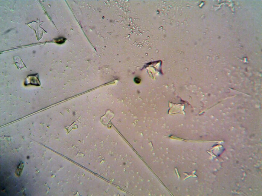
Membrane geometry should follow the feed, not the supplier's stock list. The three dominant UF formats in 2026 each own a feed window:
- Hollow fiber — the default for low-to-mid TSS industrial and municipal feeds; consistent backwash and air scour keep the fiber bundle mobile. A 0.03 μm PVDF hollow-fiber skid covers the 2,000–40,000 L/h envelope that most 2026 buyers will be quoted against (HydropureWater verified product catalog).
- Tubular — used for high-solids industrial waste where the channel geometry tolerates coarse particulates and the feed cannot be polished to low TSS.
- Flat sheet — dominant inside submerged MBR cassettes for biological streams, where the membrane sits in mixed liquor and the air-scour duty is provided by the aeration system.
Material selection is more settled. PVDF is the 2026 default for chemical resistance, mechanical strength and tight pore distribution. The HydropureWater UF skid uses 0.03 μm PVDF hollow fibers (HydropureWater verified product catalog), which sits at the tight end of the UF band; the 0.03–0.05 μm window is the practical sweet spot for wastewater, because tighter pores (≤0.01 μm) start to behave like nanofiltration and pay an energy and pressure penalty that a UF budget should not absorb.
Above 40,000 L/h on a single skid, designers parallel skids rather than oversize membranes — paralleling preserves the backwash and CIP logic that each individual skid is designed around. Sizing past a single skid's envelope without paralleling is a common RFQ error and it forces a custom vessel, custom piping and a maintenance procedure that the supplier's standard SOP does not cover.
| Geometry | Typical feed TSS window | Best-fit application | Key trade-off |
|---|---|---|---|
| Hollow fiber (PVDF) | Low to mid TSS | Industrial reuse, RO pretreatment, municipal polishing | Needs consistent backwash; intolerant of gross solids |
| Tubular | High TSS, oily feeds | Metal finishing, oily wastewater, food processing | Higher CAPEX per m²; lower flux density |
| Flat sheet (submerged) | Mixed liquor / biological | MBR duty, high-strength biodegradable streams | Air-scour tied to aeration design; not a standalone UF product |
Core Design Parameters: Flux, Recovery, TMP and Backwash
Flux (L/m²·h) and recovery (%) are the two parameters most often left vague in RFQs, and the published wastewater literature gives a defensible design window for both. Typical UF recovery sits between 70% and 90% (Water & Wastewater, 2025), and flux is a function of membrane area, feed quality and TMP. Rather than picking a number from habit, anchor TMP to the feed: optimum values are reported for 20 mg/L and 50 mg/L suspended solids feeds (Membranes and Membrane Technologies, 2020), giving the designer a starting operating point that the supplier must then verify against the actual feed.
The fouling-control rule from the same research is the missing piece in most specifications: a corrective backwash should be scheduled once flux has dropped 25% from baseline, with extra backwashes added at high-pressure duty to recover plugged pores (Membranes and Membrane Technologies, 2020). Encoding this as a parameter — not as an operational footnote — is the difference between a UF skid that runs five years and one that runs five months.
Air-scour and aeration rate (AER, m³ air / m² membrane area · h) belong in the same parameter table, not in a separate mechanical sheet. The reference configuration is automatic backwash combined with air scour on a hollow-fiber module (HydropureWater verified product catalog); this is the cheapest way to keep the membrane surface mobile and is the first defense against pore plugging. Membrane life is typically 5–10 years, conditional on influent quality, operating conditions and maintenance discipline (Water & Wastewater, 2025) — that range becomes the membrane-replacement line in the lifecycle cost model.
| Parameter | Design value or trigger | Source |
|---|---|---|
| Pore size | 0.03–0.05 μm (UF sweet spot); ≤0.01 μm behaves as NF | Industry convention; S6 |
| Recovery | 70%–90% | Water & Wastewater, 2025 |
| TMP — anchor case 1 | Optimum reported for 20 mg/L TSS feed | Membranes & Membrane Technologies, 2020 |
| TMP — anchor case 2 | Optimum reported for 50 mg/L TSS feed (conservative) | Membranes & Membrane Technologies, 2020 |
| Backwash trigger | Schedule corrective backwash once flux declines 25% from baseline | Membranes & Membrane Technologies, 2020 |
| Air scour / AER | Continuous air scour during backwash; AER sized per module | HydropureWater verified product catalog |
| Membrane life | 5–10 years, conditional on feed and maintenance | Water & Wastewater, 2025 |
| Feed turbidity cutoff | Up to 300 ppm on 0.03 μm PVDF hollow-fiber skid | HydropureWater verified product catalog |
Pretreatment and Process Train: When UF Stands Alone vs. Paired with RO or MBR
The 2026 buying question is not "do I need UF?" — it is "is UF enough, or do I need RO or MBR behind it?" The answer is set by the discharge or reuse target, not the membrane preference.
Standard pretreatment sequencing: rotary bar screen → grit removal → DAF pre-treatment for FOG, colloids or emulsified oil → equalization → UF. The DAF step is reserved for feeds that carry oil, grease or high colloidal load; for a clean low-TSS industrial feed, DAF is skipped.
The decision rules:
- UF stands alone when the target is suspended solids, turbidity, bacteria and virus reduction. The roughly 99% bacteria and 95% virus removal performance (Water & Wastewater, 2025) is the ceiling for a UF-only train. Cooling-water makeup, irrigation and many industrial reuse targets sit inside this envelope.
- UF + RO when the discharge or reuse target includes dissolved salts, TDS reduction, trace contaminants or a conductivity limit. UF becomes a pretreatment to industrial RO polishing to protect the RO membrane from fouling, and the combined train is required for boiler feed, high-pressure process water and most reuse-for-boiler duties (Water & Wastewater, 2025).
- UF inside an MBR when the upstream stream is domestic or high-strength biodegradable wastewater. A submerged PVDF MBR system delivers sub-1 μm effluent from biological treatment in a much smaller footprint than a conventional activated-sludge + UF train.
| Process train | Influent profile | Discharge / reuse target | Role of UF |
|---|---|---|---|
| UF only | Low-to-mid TSS, low FOG | Bacteria/virus reduction, reuse, cooling makeup | Terminal barrier |
| UF → RO | Any UF-compatible feed with a TDS or salinity limit | Boiler feed, high-purity process water, trace contaminant limits | RO pretreatment / fouling control |
| MBR (with UF flat sheet) | Domestic or high-strength biodegradable wastewater | Tight TSS/BOD effluent, water-reuse permitting | Solid–liquid separation inside the bioreactor |
Fouling Control and CIP Strategy: Designing the Maintenance Envelope
Fouling is the line item that breaks UF economics when it is left to operations. Fouling drives an average of about $1.25 million per year in maintenance cost at large-scale facilities (International Journal of Environmental Science, cited in Water & Wastewater, 2025). The design response is to encode the 25%-flux-decline backwash rule as a first-class parameter, and to size the air-scour and CIP chemistry around it before the skid is purchased, not after.
The CIP protocol follows the same trigger. Once flux has declined 25% from baseline, schedule a corrective backwash; if the flux does not recover, escalate to a clean-in-place with chemistry matched to the foulant (Membranes and Membrane Technologies, 2020). On industrial feeds, the foulant is rarely a single species — it is usually a mix of biological growth, colloidal silica and oil — so the CIP recipe should be specified in the RFQ, not invented by the maintenance team six months in. Automatic backwash combined with air scour is the reference configuration on a 0.03 μm PVDF hollow-fiber skid (HydropureWater verified product catalog), and pairing it with an automatic chemical dosing system for CIP keeps the recipe consistent.
One design-time addition that pays for itself inside the first year: a turbidity or particle-count sensor on the permeate line, used to validate the 25%-flux trigger against a real effluent quality signal rather than inferred from the timeline. A flux decline that does not show up on the permeate quality meter is reversible fouling; one that does is permanent plugging and the CIP recipe needs to change.
Cost, Risk and Sizing: What to Put in the RFQ
UF plants carry a real CAPEX premium. A London case study cited in Water & Wastewater (2025) puts the capital expenditure for ultrafiltration plants at 20% to 50% above conventional systems. That premium is the line item the supplier must justify with quantified membrane life, chemistry savings and the 40% coagulant reduction reported in the American Water Works Association research (Water & Wastewater, 2025). Without those numbers in the proposal, the premium is just a price.
The OPEX line items the RFQ should request, with the units specified:
- Energy per m³ permeate (kWh/m³)
- Chemical consumption (kg per CIP cycle and per m³ permeate)
- Membrane replacement, amortized over the 5–10 year service life (Water & Wastewater, 2025)
- Fouling-maintenance budget, benchmarked against the $1.25M/yr large-facility average (Water & Wastewater, 2025)
Market context matters for lead-time planning. The wastewater UF market is projected to grow at an 8.5% CAGR from 2022 to 2032 (industry analysis cited in Water & Wastewater, 2025), so lead times and pricing should be assumed to tighten through 2026 — a 12-week delivery window in 2024 may not hold in 2027. Sourcing through a vetted channel is one way to manage that risk; the 2026 North American sourcing guide covers how to evaluate suppliers against that backdrop.
Final sizing sanity check before signing: confirm that the proposed flow — typically 2,000–40,000 L/h on a single 0.03 μm PVDF hollow-fiber UF skid — actually matches the duty, that the redundant-skid philosophy is defined (N+1 vs. N+2), and that spare-membrane holding cost is priced. The 2026 MBR O&M manual covers the parallel operating logic for plants where UF sits inside an MBR rather than as a standalone barrier.
Frequently Asked Questions
What CAPEX and OPEX should I expect for a 2026 industrial UF skid?
Capital expenditure for a UF plant runs 20% to 50% above a conventional system of equivalent throughput, per a London case study cited in Water & Wastewater (2025). For OPEX, the line items to request from suppliers are energy per m³ permeate, chemical consumption, membrane replacement amortized over a 5–10 year service life, and a fouling-maintenance budget benchmarked against the $1.25M/yr large-facility average reported in the International Journal of Environmental Science (cited in Water & Wastewater, 2025). Ask for each of those numbers in writing, with units, before accepting a quote.
How do I size a UF skid and pick the right supplier for my influent?
Sizing starts with the feed data set (TSS, turbidity, FOG, COD/BOD, pH, chlorine residual, particle size distribution) and a TMP anchor at either 20 mg/L or 50 mg/L TSS, since optimum TMP values are reported for both of those suspended-solids levels (Membranes and Membrane Technologies, 2020). On the equipment side, a single skid family typically covers 2,000–40,000 L/h on 0.03 μm PVDF hollow fibers, with parallel skids for higher flows. For supplier selection, request documented membrane life on similar feeds, a written CIP recipe matched to your foulant, and proof the proposed flow matches your duty with the redundant-skid philosophy defined — the 2026 North American sourcing guide lays out the evaluation checklist.
When does UF need to be paired with RO or MBR rather than standing alone?
UF stands alone when the target is suspended solids, turbidity, bacteria (≈99% removal) and viruses (≈95% removal), per Water & Wastewater (2025). Pair UF with an industrial RO polishing train when the target includes dissolved salts, TDS reduction or trace contaminants — UF becomes RO pretreatment. Use a submerged PVDF MBR system when the upstream stream is domestic or high-strength biodegradable wastewater and a compact biological + separation train is required. Anything stricter than the UF-only ceiling — boiler feed, high-purity process water, tight reuse permitting — needs downstream polishing.
What is the 25%-flux-decline backwash rule and why does it belong in the spec?
The rule is that a corrective backwash is scheduled once flux has dropped 25% from baseline, with extra backwashes added at high-pressure duty to recover plugged pores (Membranes and Membrane Technologies, 2020). It belongs in the written specification because it converts fouling control from an operational footnote into a trigger the controls system can act on. Pair it with continuous air scour and a permeate-side turbidity or particle-count sensor so the trigger is validated against real effluent quality, not inferred from the clock.