
What an Electrocoagulation System Does (and Why It Fails)
Electrocoagulation (EC) dissolves sacrificial iron or aluminum anodes in place — no external coagulant drum required. Current flowing through the cell releases Fe³⁺ or Al³⁺ ions, which hydrolyze into metal-hydroxide floc (Fe(OH)₃ or Al(OH)₃) and attach to dissolved and colloidal contaminants, producing settleable solids (Racoman, "Electrocoagulation: Wastewater Treatment Explained"). The same current also evolves H₂ at the cathode, which buoys fine floc to the surface. Every symptom an operator reports — brown effluent, hot cell, no settling, foam at the weir — traces back to one of four knobs drifting off-spec: current density (typically 10–150 mA/cm²), pH (5–9 for Al, 5–8 for Fe), chloride (≥50 mg/L Cl⁻), or influent composition. This article addresses seven recurring field problems against that framework and links them to the downstream DAF, lamella, or filter press train.
Quick-Reference: Symptom → Likely Cause Matrix
The matrix below helps operators triage panel readings before performing manual maintenance.
| Symptom at the panel or in the jar | Most likely cause | Jump to |
|---|---|---|
| Voltage climbs 15–20% at the same current, flow unchanged | Electrode passivation (insulating oxide film) | Problem 1 |
| Cell runs hot, kWh/m³ doubled or more | Scaling (CaCO₃/Mg(OH)₂) or low feed conductivity | Problem 2 |
| Clear effluent but metals still above limit | pH outside the floc-stability window or under-current | Problem 3 / 5 |
| Foam at the weir, floating sludge escapes | Surfactants + H₂ entrainment, current density too high | Problem 4 |
| Sludge blanket overflows the clarifier | Downstream separator undersized for EC floc volume | Problem 6 |
Reference ranges used throughout: current density 10–150 mA/cm², pH 5–9 (Al) / 5–8 (Fe), Cl⁻ ≥50 mg/L, and energy 0.5–5 kWh/m³ under normal duty, climbing past 10 kWh/m³ at >95% metal-removal targets (Racoman).
Problem 1: Electrode Passivation and Falling Removal Efficiency
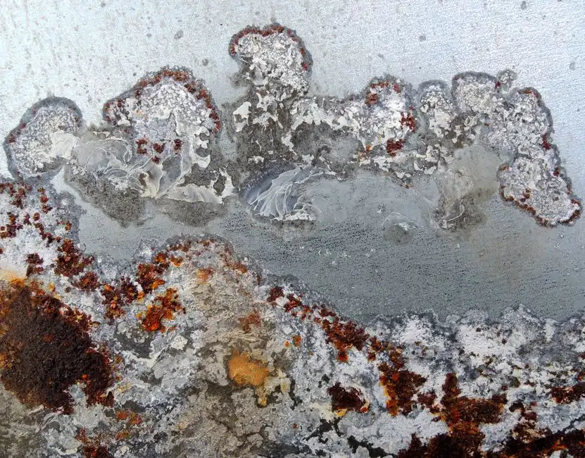
Passivation is the most common field failure and the first condition to rule out when a cell goes off-spec. The mechanism is straightforward: an insulating oxide film — Fe₂O₃ on iron, Al₂O₃ on aluminum — grows on the anode surface, raising cell voltage and starving the reaction of current (Racoman notes electrodes "degrade due to the electrolysis process" and lose efficiency over time). Diagnostic: compare applied voltage against the as-commissioned baseline at the same current setpoint. A rise of >15–20% with unchanged feed and flow indicates passivation, not scaling. Fix 1 — Polarity reversal (PR): automated anode/cathode switching every 5–30 minutes is built into most modern EC cells; it consumes the film on the now-cathode side. Fix 2 — Acid wash: recirculate 5–10% HCl or H₂SO₄ for 30–60 minutes, then rinse to neutral pH; this strips the oxide without damaging the base metal. Fix 3 — Boost conductivity: dose NaCl or KCl to 0.5–3 g/L so chloride ions electrochemically break down the passive layer (Racoman confirms chloride-rich feed extends electrode life). Prevention: install PR as standard, keep Cl⁻ ≥50 mg/L, and avoid long idle periods where the anode sits dry or under polarized DC.
Problem 2: Scaling, Hard-Water Deposits, and Rising Energy Use
Hard-water scaling occurs when Ca²⁺ and Mg²⁺ precipitate as CaCO₃ or Mg(OH)₂ on the cathode under high-pH, high-temperature conditions. Sulfate-rich feed can also drop CaSO₄. Diagnostic: a white, chalky crust on the cathode (vs. the dark, glassy oxide of passivation on the anode) and feed hardness >500 mg/L as CaCO₃. Fix: pre-soften with an industrial water softener sized for 1–45 m³/h EC feed, dose anti-scalant, lower current density to 10–30 mA/cm², and clean cathodes with 2–5% citric acid to dissolve carbonate without attacking the underlying metal. Energy context: EC is energy-intensive and the bill scales with required removal (Racoman); expect 0.5–5 kWh/m³ in normal duty and 10+ kWh/m³ when chasing >95% metal targets. If the kWh/m³ number is climbing faster than the removal rate, scaling is the prime suspect.
Problem 3: pH Drift, Poor Floc Formation, and 'Nothing Settles'
Bulk pH usually climbs 0.5–1.5 units as EC runs because cathode reduction consumes H⁺ and anode oxidation releases it locally. Outside the metal-hydroxide stability window, the floc simply re-dissolves — Racoman lists pH as a primary efficiency driver alongside current and influent composition. Target windows: aluminum electrodes pH 5–9, iron electrodes pH 5–8. Below the window the metal stays in solution as a free ion; above it the hydroxide resolubilizes as aluminate or ferrate. Fix: install online pH control with an automatic pH and chloride dosing skid — dose H₂SO₄ or HCl when pH climbs above the window, and NaOH when the feed is strongly acidic. If floc is forming but not settling in the clarifier, the issue is likely downstream.
Problem 4: Foam, Floating Sludge, and Gas Entrainment
Hydrogen evolution at the cathode entrains fine floc and surfactants, creating a buoyant mat that rides over the clarifier weir and recontaminates effluent TSS. Diagnostic: jar-test for surfactants using a foaming-height cylinder, and check current density — above ~80 mA/cm² gas evolution becomes excessive and the mat worsens. Fix ladder: (1) reduce current density into the 30–60 mA/cm² band, (2) dose anti-foam (silicone or fatty alcohol) sparingly at the cell outlet to prevent fouling downstream membranes, and (3) install a dedicated dissolved air flotation (DAF) skimmer for 4–300 m³/h duty to capture the float layer. Food, textile, and metalworking plants running surfactants should treat DAF as a standard auxiliary rather than an upgrade.
Problem 5: High Effluent Metals or COD Despite a Healthy Cell

The "panel says green, lab says no" problem typically results from pH drift, under-current, or feed concentration exceeding the capacity of a single EC pass. Racoman notes removal efficiency depends on "type and concentration of contaminants" and confirms high removal of lead, copper, nickel, and chromium. Diagnostic: check influent concentration against the design basis and verify current density sits in the 50–150 mA/cm² band used for heavy-metal polishing. Fix ladder: (1) extend residence time in the cell, (2) raise current density incrementally while monitoring the kWh/m³ curve, and (3) add a polishing stage — an MBR membrane bioreactor for sub-1 µm capture of residual colloids, or a multi-media filter for TSS-bound residuals. Because EC energy demand scales with target removal (Racoman), a polishing stage is often more economical than increasing current density to chase the final 5–10% of metals.
Problem 6: Downstream Solids Overload and Sludge Handling
EC sludge is lower in volume than chemical-coagulation sludge (Racoman), but it is light and gelatinous, which can overwhelm a conventional clarifier sized for heavy chemical-sludge blankets. The fix is to route EC effluent through a purpose-built separator: a lamella clarifier for EC floc at 20–40 m/h surface loading, or a DAF unit for 4–300 m³/h duty. Dewatering: a plate and frame filter press for EC sludge in the 1–500 m² filtration-area range brings cake to 25–35% dry solids. Pollution-prevention note: do not recycle EC sludge to a biological stage, as the metal-hydroxide floc will upset MLSS and knock nitrification offline. For a side-by-side view of where EC fits against other plant equipment, the industrial water treatment system comparison covers the full train, while the disinfection equipment troubleshooting guide covers post-treatment failures.
Operating Parameter Reference Table
Print this table and post it near the MCC for quick reference of standard industry windows for sacrificial-electrode EC cells; the energy and removal figures are drawn from Racoman.
| Parameter | Typical operating range | Notes |
|---|---|---|
| Current density | 10–150 mA/cm² | 10–30 for scaling feeds; 50–150 for heavy-metal polishing |
| pH window | 5–9 (Al) / 5–8 (Fe) | Outside the window the hydroxide floc redissolves |
| Chloride (Cl⁻) | ≥50 mg/L; target 0.5–3 g/L as NaCl | Cl⁻ breaks down passive films; chloride-rich feed extends electrode life |
| Electrode gap | 5–20 mm | Tighter gap = lower voltage, higher current density at same kW |
| Residence time | 10–60 min | Longer for high-COD or polishing duty |
| Energy use | 0.5–5 kWh/m³ normal; 10+ kWh/m³ at >95% metal targets | Scales with required removal efficiency (Racoman) |
| Electrode life | 1–5 years with PR | Depends on feed composition, current, and Cl⁻ (Racoman) |
Frequently Asked Questions
How often should EC electrodes be replaced?
Replacement frequency depends on electrode type (Fe vs. Al), wastewater composition, volume treated, and applied current (Racoman). With polarity reversal in place and Cl⁻ held at ≥50 mg/L, a typical service life is 1–5 years; without PR, expect the low end or below.
Why is my EC cell using so much electricity?
The kWh/m³ number climbing without a matching rise in removal typically indicates voltage is climbing at the same current setpoint. Consult the Quick-Reference matrix: passivation (Problem 1), scaling (Problem 2), or low feed conductivity are the most likely causes. Check baseline voltage first, then hardness, then conductivity.
Can electrocoagulation treat heavy metals?
Yes — Racoman confirms high removal of lead, copper, nickel, and chromium via formation of insoluble metal hydroxides. The pH window must remain at 5–8 (Fe electrodes) or 5–9 (Al electrodes) for the floc to form and remain insoluble.
What is the biggest cause of poor floc?
pH outside the metal-hydroxide stability window. While coagulant ions are released correctly, the hydroxide that drives settling redissolves, resulting in a clear cell with no floc and no removal. Online pH control typically resolves this issue.
Is EC sludge easier to handle than chemical coagulation sludge?
Yes — Racoman notes EC sludge is less voluminous and easier to manage because no counter-ions from a chemical coagulant are added. It still requires dewatering in a filter press or drying bed before disposal and should never be recycled to a biological stage, as the metal hydroxide will upset MLSS.