Why UPW System Design Now Sits on the Critical Path for US CHIPS Act Fabs
Power and water are the two binding physical constraints on US CHIPS Act fab site selection, and for the 2026 buildout, water is the more geographically limiting of the two: power can be moved by building a new transmission line, while UPW requires a local watershed capable of sustaining 2–10 MGD of net withdrawal under drought-year conditions, and a municipal or reclaimed source that can actually deliver that volume. A leading-edge 300 mm fab consumes 10–20 MGD of UPW at full ramp (per the 2026 fab operations reference on semiconductorx.com) and recycles 50–80% at best-in-class sites, leaving 2–10 MGD of net withdrawal that drives community, regulatory, and water-rights tension. That tension is already binding: TSMC's Arizona Fab 21 design incorporates a 100% recycle target and ZLD for cooling-tower blowdown not because Taiwan practice requires it, but because Colorado River allocation under sustained shortage leaves no alternative.
The procurement pattern has hardened in parallel. The Gradiant/H+E Germany award, valued as part of an approximately $120 million project backlog and announced January 2024, packaged a complete UPW plant as a single full-train EPC contract under the European Chips Act (source: waveep.com, 2024-01). US fabs should expect the same one-shot, full-train award model in 2026–2028, which means the UPW system is no longer a utility ordered after the fab shell is up — it is a long-lead, parallel-track CAPEX line that has to be locked in during phase 1 of fab construction. The four flagship US CHIPS Act geographies (Arizona, Ohio, Oregon, and Texas/New York) face materially different water-stress profiles, and a single UPW design does not fit all of them. The decision matrix that follows ties each design choice (EDI vs mixed-bed, hot vs ambient loop, ZLD vs high-recovery RO) to the water profile of the specific site being built.
The 2026 UPW Specification: What a CHIPS Act Fab Must Actually Hit
The 2026 UPW spec is a parameter-tightening exercise, not a wholesale reinvention. The targets below are what a leading-edge fab at N3–N5 must hit continuously at point of use, and each parameter tightens visibly from a 2015-class fab because device features are now smaller than the contaminants the water must reject.
| Parameter | 2026 leading-edge target | Failure mechanism if missed |
|---|---|---|
| Resistivity | 18.2 MΩ·cm (theoretical max at 25 °C) | Metal-ion deposition at ppb level causes junction leakage, DRAM retention failure, and gate-oxide integrity loss |
| Total organic carbon (TOC) | <1 ppb (μg/L) at EUV nodes; SEMI E-1.3 / UPW grade | Organic contamination of photoresist and EUV optics; gate-dielectric defects |
| Dissolved oxygen (DO) | <1 ppb | Native-oxide growth on silicon surfaces during cleaning; device electrical drift |
| Silica (SiO2) | Low ppb; <5 ppb post-EDI | Silica deposition during drying; threshold-voltage shift and leakage current |
| Particles | <1/mL at >0.05 μm | A 50 nm particle is roughly 17× larger than a 3 nm feature — single-particle killer defects |
| Bacteria | <1 CFU/100 mL; continuous UV sterilization | Biofilm in distribution piping releases particles and TOC continuously |
| Trace metals (Na, K, Ca, Fe, Cu) | Sub-ppb, ideally <0.1 ppb post mixed-bed | Deep-level traps in silicon; Cu and Fe are the most damaging |
The 18.2 MΩ·cm figure is the theoretical maximum resistivity of pure H2O at 25 °C; hitting it in a distribution loop that is continuously recontaminating itself from biofilm, joint leaching, and pump wear is the engineering problem (per the 2026 fab operations reference, semiconductorx.com). TOC has tightened by roughly four orders of magnitude from the EPA 4 mg/L (4,000 ppb) limit, which is the spec for drinking water, not wafers. The iScience 2025 review on semiconductor wastewater (source: sciencedirect.com, 2025-10) notes that the growing complexity of fab wastewater composition is forcing UPW designers toward minimal-liquid-discharge architectures that integrate forward with the recycle side of the plant. Critically, UPW cannot be stockpiled, cannot be trucked in, and cannot be purchased off-spec — it is a continuous-operation facility housed in a dedicated utility building adjacent to the fab, and a system failure stops wafer production within hours regardless of the status of every other fab system.
The Six-Stage UPW Train: Stage-by-Stage Design Choices
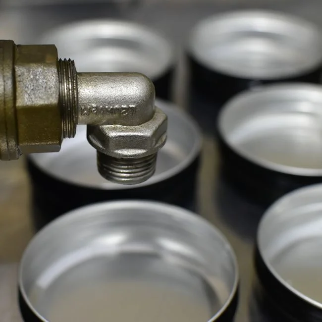
A 2026 UPW train is six stages, each removing a specific contaminant class, with the design choice at each stage cascading into CAPEX, OPEX, and site fit. The pretreatment and final-polish stages are largely fixed by feed-water quality and POU spec; the choice points that actually drive cost and site fit are Stages 2 through 5.
| Stage | Function | Design choice / target |
|---|---|---|
| 1 — Pretreatment | Multimedia filtration, activated carbon, softening | Turbidity <0.1 NTU; chlorine <0.1 ppm to protect RO membranes (per fab operations reference); antiscalant dosing |
| 2 — Reverse osmosis | Bulk ionic load rejection | Single-pass vs two-pass: two-pass RO reaches ~1–5 MΩ·cm and protects downstream polishing from bulk ionic load; 150–300 psi operating pressure; antiscalant required |
| 3 — Primary polishing | Residual ion removal to ppb | EDI vs mixed-bed DI: EDI delivers 15–17 MΩ·cm and silica <5 ppb continuously with no acid/caustic regeneration; mixed-bed hits the same spec but generates regeneration wastewater |
| 4 — UV oxidation | TOC reduction + bacterial sterilization | Dual-wavelength 185/254 nm lamps oxidize TOC to CO2; 254 nm sterilizes; downstream CO2 degassing required; TOC <1 ppb at POU |
| 5 — Vacuum / membrane degassing | Dissolved gas removal | Hollow-fiber contactors (3M Liqui-Cel type) or vacuum towers drive DO <1 ppb to suppress native oxide growth |
| 6 — Final polish (POU) | Mixed-bed DI + UF | Residual ions to <0.1 ppb; particles >0.02–0.05 μm removed by UF; continuous recirculation loop maintains quality — most operational defects originate here |
Two design choices dominate. The first is single-pass vs two-pass RO: single-pass reaches ~0.5–2 MΩ·cm and is acceptable only when downstream mixed-bed DI is sized to absorb the bulk ionic load, which inflates regeneration chemical OPEX; two-pass RO reaches ~1–5 MΩ·cm and is the 2026 default for greenfield fabs because it lets downstream continuous EDI stacks for UPW polishing run at design loading without scaling or fouling. The second is EDI vs mixed-bed DI: EDI's selling point is continuous operation with no acid/caustic regeneration, which is a meaningful simplification for any site pursuing 100% recycle — EDI eliminates the regeneration wastewater stream that mixed-bed DI produces. For Arizona, that difference is decisive; for Ohio and Oregon, it is a preference, not a requirement.
Design Choice Matrix: EDI vs Mixed-Bed, Hot vs Ambient Loop, ZLD vs High-Recovery RO
Three binary design choices cascade into CAPEX, OPEX, and site fit. Engineers should treat this matrix as the first procurement filter: any answer that contradicts the site water profile should be revisited before the request-for-quote goes out.
| Design choice | Option A | Option B | 2026 default / site driver |
|---|---|---|---|
| Primary polishing | EDI (15–17 MΩ·cm, no regen chemicals) | Mixed-bed DI (18.2 MΩ·cm, acid/caustic regen) | EDI for water-stressed sites and 100% recycle targets; mixed-bed acceptable where regeneration wastewater is handled by existing neutralization |
| Distribution loop | Hot loop (~60–80 °C) — suppresses biofilm, higher energy and material cost | Ambient loop — cheaper to build, requires aggressive UV/ozone | Hot loop in water-stressed sites (Arizona, central Texas) where any biofilm event is a yield event; ambient loop acceptable in Ohio and Oregon with robust UV |
| Concentrate management | ZLD — evaporators/crystallizers, near-zero liquid discharge, high CAPEX | High-recovery RO with cooling-tower blowdown reuse | ZLD in Arizona (Colorado River basin, Lake Mead/Powell historically low); high-recovery RO sufficient in Ohio and Oregon |
| RO architecture | Single-pass RO | Two-pass RO via two-pass industrial RO systems | Two-pass for greenfield fabs; single-pass only for capacity expansions on existing single-pass trains |
The downstream consequences are concrete. EDI eliminates the regeneration wastewater stream that mixed-bed DI produces, which simplifies the recycle-side mass balance for any site pursuing 100% reuse — TSMC's Arizona target is the headline example. Hot loops suppress bacterial growth without continuous chemical biocide dosing, but require elevated-temperature-rated PVDF or PFA piping and heat-exchanger capacity, which is why ambient loops remain the lower-CAPEX default in water-abundant regions. ZLD versus high-recovery RO is the most site-sensitive of the three: in the Colorado River basin, ZLD for cooling-tower blowdown is now effectively mandatory for political and regulatory reasons, not optional sustainability theater.
Site Water Profile: How the Four Flagship US CHIPS Act Geographies Change the Design
Water profile, not labor cost or power cost, is the variable that should drive which design choices a given fab locks in. The four flagship US CHIPS Act geographies span a water-stress gradient from extreme (Arizona) to abundant (Oregon, New York), and the design spec should track that gradient.
| Site | Water source / supply | Stress level | Design implication |
|---|---|---|---|
| TSMC Arizona Fab 21 (Phoenix) | City of Phoenix municipal; Colorado River (Central Arizona Project); Salt River Project reclaimed water | Extreme — Sonoran Desert; Colorado River basin under sustained multi-decade shortage; Lake Mead/Powell historically low | 100% recycle target; reclaimed water as primary makeup; ZLD for cooling-tower blowdown; recycle and UPW are one integrated design, not two |
| Intel Ohio (Licking County) | Columbus municipal; Licking County groundwater; Big Walnut Creek watershed | Low–moderate — Ohio River watershed, abundant freshwater | Net positive water commitment means the design must over-spec recycle and effluent quality beyond discharge requirements; no ZLD required |
| Intel Oregon (Tualatin Valley) | Tualatin Valley Water District; Tualatin River watershed | Low — Pacific Northwest, abundant precipitation | Reference design for what is achievable without ZLD: >80% reuse publicly reported; the high-water-recovery benchmark for the US industry |
| Samsung Taylor (Texas) | City of Taylor municipal; Little River / Brazos basin; Granger Lake | Moderate — central Texas has drought cycles; growth-stressed region | Samsung partners with City of Taylor and Williamson County on water infrastructure expansion; reclaimed water targeted for cooling; design should bias toward recycle-heavy even though ZLD is not yet required |
| Micron Clay (New York) | Onondaga County Water Authority; Oneida Lake / Oswego River | Low — abundant freshwater; Great Lakes basin proximity | Lowest-risk water position in the CHIPS Act portfolio; favorable supply is a stated site-selection factor; standard high-recovery RO without ZLD |
The pattern that emerges: the more water-stressed the site, the more the UPW system and the recycle/ZLD system must be designed as one plant, not two. In Arizona, the UPW polish train and the ZLD crystallizer share a mass balance, and changing one without re-running the other is a design error. In Oregon and New York, the two systems can be specified and procured on separate tracks.
CAPEX, OPEX and Supplier Landscape for a 2026 US Fab UPW System
CAPEX for a 2026 leading-edge fab UPW system runs $200–500M for the primary production train, plus $50–150M for the recycle and concentrate-management system (per the 2026 fab operations reference). Combined, that is $250–650M of long-lead utility CAPEX that must be ordered during phase 1 of fab construction, not after the shell is up. OPEX is dominated by two line items: energy for the two-pass RO high-pressure pumps and the vacuum degassing vacuum pumps, and chemicals — antiscalant for RO membranes, and acid/caustic regeneration if mixed-bed DI is selected over EDI.
| Supplier | HQ | Role / differentiation |
|---|---|---|
| Evoqua Water Technologies (Xylem) | Pittsburgh, PA, USA (Xylem acquisition 2023) | Full UPW system integration; Ionpure EDI is the reference technology for North American fabs; strong domestic service network |
| Kurita Water Industries | Tokyo, Japan | Dominant at TSMC, Sony Semiconductor, Kioxia; equipment plus on-site chemical service model; the Asian-fab reference |
| Veolia Water Technologies | Paris, France (with strong European fab presence) | Full UPW EPC; ZLD expertise directly relevant to Arizona and Texas sites; broad portfolio including MBBR for organic waste streams |
| Gradiant / H+E Group | Boston, MA, USA / Stuttgart, Germany | Full-train EPC; reference: H+E Germany award under the European Chips Act, ~$120M project backlog (source: waveep.com, 2024-01); single-contract delivery model is the template for 2026 US awards |
| DuPont Water Solutions (FilmTec) | Wilmington, DE, USA | RO membrane and ion-exchange resin component supplier to all integrators; FilmTec is the reference RO membrane product |
| Toray Industries (Water Treatment) | Tokyo, Japan | RO and UF membrane supply; complete membrane-based systems; Asian fab focus |
For pretreatment and point-of-use polish, North American fabs typically pair multi-media pretreatment filters with PVDF ultrafiltration at point of use as the standard Stage 1 and Stage 6 hardware. The Gradiant/H+E Germany award is the operational precedent: policy-driven fab buildouts are now packaged as single full-train EPC contracts, and US CHIPS Act fabs should expect the same delivery model in 2026–2028, with one supplier taking mechanical, electrical, and process guarantee across the entire train from pretreatment through POU polish.
Frequently Asked Questions
What resistivity, TOC and DO targets define a 2026 CHIPS Act UPW spec?
A 2026 leading-edge fab must hit 18.2 MΩ·cm resistivity, <1 ppb TOC, and <1 ppb dissolved oxygen continuously at point of use (per SEMI E-1.3 and the 2026 fab operations reference). The TOC target is roughly four orders of magnitude tighter than the EPA 4 mg/L drinking-water limit, and the DO target exists specifically to suppress native-oxide growth on silicon surfaces during cleaning.
How much does a UPW system cost for a US CHIPS Act fab in 2026?
Primary UPW system CAPEX runs $200–500M per leading-edge fab, with an additional $50–150M for the recycle and concentrate-management system, for a combined $250–650M of long-lead utility CAPEX ordered during phase 1 of fab construction. The wide range reflects site water stress: Arizona-style ZLD-inclusive designs sit at the top of the band; Ohio/Oregon designs without ZLD sit at the bottom.
Which US CHIPS Act fab has the most aggressive water recycling target, and why?
TSMC Arizona Fab 21 has committed to 100% water recycling, driven by Colorado River basin allocation under sustained multi-decade shortage rather than Taiwan practice. Intel Oregon has already achieved >80% reuse at its Tualatin Valley site and is the operational benchmark for high-recycle UPW design without ZLD, per the 2026 fab operations reference.
What is the right RO architecture for a 2026 greenfield fab?
Two-pass RO via two-pass industrial RO systems is the 2026 default for greenfield leading-edge fabs, reaching ~1–5 MΩ·cm and protecting downstream EDI from bulk ionic load. Single-pass RO is acceptable only for capacity expansions on existing single-pass trains where downstream mixed-bed DI is already sized to absorb the load.
How does site water stress change the choice between EDI and mixed-bed DI?
EDI is the right default at water-stressed sites pursuing 100% recycle because it eliminates the acid/caustic regeneration wastewater stream that mixed-bed DI produces, simplifying the recycle-side mass balance. Mixed-bed DI remains acceptable in water-abundant regions with existing neutralization capacity, but the OPEX penalty from regeneration chemicals and wastewater handling tends to dominate the analysis over a 20-year lifecycle, as detailed in our 20-Year Lifecycle Cost Estimation for UPW Systems (2026 Guide).
Why is piping material a hidden CAPEX line on US CHIPS Act fabs?
UPW distribution piping is the source of most operational defects because biofilm, joint leaching, and pump wear continuously recontaminate the loop. Hot-loop designs in water-stressed sites require elevated-temperature-rated PVDF or PFA piping, which materially changes the CAPEX line; the long-term cost data and PFAS-free alternatives are covered in Georg Fischer UPW Piping Systems for Semiconductor Fabs: 2026 Long-Term Cost Data & PFAS-Free Alternatives. For the broader wastewater side, the variable-chemistry design problem is treated in Semiconductor Wastewater Treatment System Design for Variable Waste Chemistry (2026 Engineering Guide), and the integrated circuit manufacturing wastewater context in Integrated Circuit Manufacturing Wastewater Treatment: 2026 Process Guide.