

The 2026 regulatory frame for a Prague semiconductor or data-hall operator
In 2026 a Prague semiconductor or data-hall facility should treat process wastewater as four segregated streams — UPW reject, CMP/dicing effluent, cooling-tower blowdown, and segregated sanitary — engineered against the EU Industrial Emissions Directive 2010/75/EU BAT-AEL envelope, Czech Water Act 254/2001 Sb., and PVK trade-effluent limits, targeting >70% on-site reuse.
Three regulatory layers bind a 2026 operator in Prague, and procurement should sequence engineering to the permit timeline rather than the other way around.
Layer one is European. The EU Industrial Emissions Directive 2010/75/EU triggers BAT-AEL effluent limits for large semiconductor fabs, with TOC, total nitrogen, total phosphorus, copper, and nickel as the headline parameters. Data halls fall under the directive only once IED Annex I capacity thresholds are crossed, but indirect discharge still binds under the EU Urban Waste Water Treatment Directive 91/271/EEC, which caps BOD, COD and total nitrogen at the connection to the Prague sewer network.
Layer two is Czech. The EU wastewater acquis is transposed in Czechia through zákon č. 254/2001 Sb. (the Water Act), which sets the §8 discharge-permit framework administered by the krajský úřad (regional authority), and vyhláška č. 428/2001 Sb., which governs wastewater sampling and analysis methods. The Water Act was amended in 2024–2025 to tighten the reuse-permit threshold; any reuse fraction above ~50% on a single stream now requires a permit amendment rather than a notification, which is the trigger to plan for in Q4 2026.
Layer three is local. PVK (Pražské vodovody a kanalizace) trade-effluent limits apply at the discharge manhole, not at the building drain. Conductivity, temperature (typically ≤35 °C at the connection), sulfate, hydrocarbons, and the same heavy-metals envelope cap the mixed stream. Cooling-tower blowdown containing oxidising biocides is classified as industrial wastewater and cannot be co-mingled with sanitary flow without pre-treatment, because the biocide load disrupts biological treatment at the receiving Prague Central Wastewater Treatment Plant on the Vltava at Císařský ostrov.
Layer four is disclosure. From FY 2026, water withdrawal, discharge and reuse become reportable metrics under CSRD ESRS E3, which means engineering choices made in 2026 will sit in a public filing. The wastewater plant is therefore a disclosure asset, not an end-of-pipe chore.
| Layer | Instrument | Headline parameters | Administering body |
|---|---|---|---|
| EU | IED 2010/75/EU + BAT-AEL | TOC, TN, TP, Cu, Ni | Operator + EU registry |
| EU | UWWTD 91/271/EEC | BOD, COD, TN (indirect discharge) | Operator + receiving plant |
| Czech | Zákon 254/2001 Sb. + vyhláška 428/2001 Sb. | §8 discharge permit, sampling methods | Krajský úřad, Povodí Vltavy |
| Local | PVK trade-effluent limits | Conductivity, T ≤35 °C, sulfate, hydrocarbons, metals | PVK a.s. at manhole |
| Disclosure | CSRD ESRS E3 | Withdrawal, discharge, reuse, intensity (m³/revenue unit) | Company + auditor |
Why Prague changes the engineering baseline
Prague's raw water is Vltava surface water with Želivka reservoir hardness ≈1.3 mmol/L (Ca+Mg) and seasonal turbidity swings from <5 NTU in winter to >40 NTU during the spring snowmelt and the Jizera tributary peaks, which forces higher cooling-tower blowdown rates than a soft-water site such as Vienna's alpine springs. Conductivity sits at 350–500 µS/cm at the plant inlet, so cycles of concentration in the cooling loop have to be set around 4–5 rather than the 6–7 typical of softer sources; this fixes the blowdown volume and the chemistry downstream.
The basin context matters because disclosure is basin-scoped. 45% of data centres globally sit in basins at high water-availability risk (TNFD, Feb 2026). Prague draws from the Vltava basin, which the Czech Ministry of Agriculture classifies as moderate-stress but legally over-allocated — total permitted abstraction exceeds mean annual flow once Želivka transfers are netted out. On-site reuse is therefore the lowest-risk path against any future basin reallocation, and the CSRD ESRS E3 disclosure will surface this exposure regardless of where the abstraction sits today.
Heat recovery interacts with the wastewater train. Pražská teplárenská district heating, which serves roughly 75% of Prague households from the Malešice, Michle and Holešovice plants, can absorb low-grade return loops from data-hall cooling, which reduces the adiabatic make-up demand and shrinks the blowdown stream by 15–25% relative to an air-cooled baseline. For a 50 MW hall in Prague 6, 8, or Horní Počernice, the heat-recovery sizing should be confirmed with Pražská teplárenská before the cooling-tower RO skid is sized, because the blowdown mass balance shifts once a heat-recovery contract is in place.
The 2026 procurement context is also domestic. The Czech Semiconductor Centre in Brno and the Czech National Semiconductor Cluster are aligning back-end and packaging investment with the EU Chips Act, and EPC briefs originating from those consortia will reach Prague process designers over 2026–2027. Treat the design point as a Czech baseline, not a Vienna import, and the permit and disclosure envelope falls into place.
The four process streams a Prague site must segregate
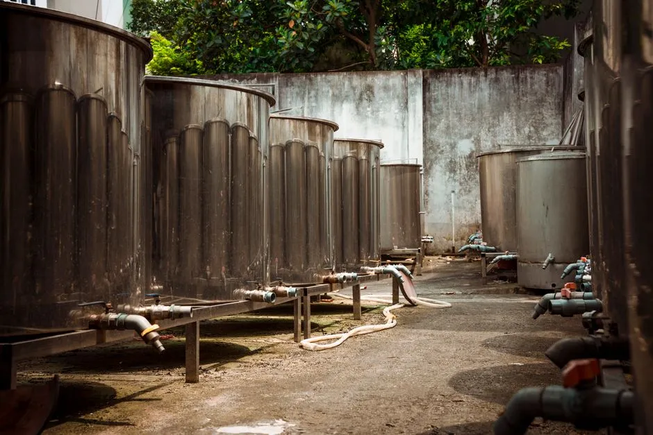
A Prague back-end fab or a 5–50 MW colocation hall should treat the site as four segregated streams that meet only at the final discharge manhole. Conflating them upstream is the single most common reason operators miss the PVK trade-effluent envelope and trigger a §8 permit amendment under zákon 254/2001 Sb.
Stream 1 — UPW reject and fab rinse water. UPW systems reject 1.4–1.6 m³ of municipal water for every 1 m³ of UPW produced (TNFD, Feb 2026). The reject stream carries resistivity dropping from 18.2 MΩ·cm toward 1–2 MΩ·cm, TOC typically >1 mg/L, and trace silica from polishing-loop regeneration. It is the cleanest industrial stream on site and the easiest to polish for reuse as cooling make-up or scrubber feed.
Stream 2 — CMP slurry, dicing and back-grind waste. This is the most chemically aggressive stream. Nano-silica particles below 150 nm, fluoride from oxide CMP at 50–500 mg/L, copper slurries at hundreds to a few thousand mg/L of suspended solids, and surfactant-laden dicing effluent dominate the characterisation. It is only present at back-end fabs; a pure colocation hall can drop Stream 2 entirely.
Stream 3 — Cooling-tower blowdown. Cooling is the dominant water consumer at data-hall sites. A typical facility uses 25 million to 770 million litres per year, and hyperscale campuses exceed 2 billion litres annually (TNFD, Feb 2026). Blowdown conductivity sits at 2,000–4,000 µS/cm, silica at 50–150 mg/L, with residual oxidising biocides. Volumes are large but the chemistry is predictable, and the Prague source-water hardness means blowdown silica cycles higher than at a soft-water site.
Stream 4 — Segregated sanitary effluent. Office, welfare and cafeteria flow follows a municipal profile — BOD 200–400 mg/L, NH₄-N 30–60 mg/L — and is governed by UWWTD 91/271/EEC when discharged to the Prague main sewer. Keeping it segregated is what unlocks MBR polishing for toilet-flushing and irrigation reuse.
| Stream | Source | Headline chemistry | Reuse / discharge destination |
|---|---|---|---|
| 1 — UPW reject | UPW system reject, fab rinse | Resistivity 1–2 MΩ·cm; TOC >1 mg/L; trace SiO₂ | Polishing RO → cooling make-up / scrubber feed |
| 2 — CMP / dicing | Back-end fab only | Nano-SiO₂ <150 nm; F⁻ 50–500 mg/L; Cu slurries 100s–1000s mg/L TSS | Precipitation + UF-RO; concentrate off-site |
| 3 — Cooling-tower blowdown | Cooling loop, adiabatic humidifiers | Cond. 2,000–4,000 µS/cm; SiO₂ 50–150 mg/L; oxidising biocide residue | Softening + RO → adiabatic make-up; residual brine to PVK manhole |
| 4 — Segregated sanitary | Office, welfare, cafeteria | BOD 200–400 mg/L; NH₄-N 30–60 mg/L | MBR → toilet flushing / landscape irrigation; surplus to PVK |
Stream-by-stream treatment train for 2026
The modular train below scales from a single 5 MW colocation hall to a hyperscale campus without changing the unit operations, only their sizing. Equipment selection at headworks is the constraint that fixes everything downstream, so start with a rotary mechanical bar screen for headworks sized for peak wet-weather flow plus a grit chamber. Upstream pH correction and coagulant dosing is handled by an automatic chemical dosing system with redundant metering pumps and inline pH/ORP probes tied to the SCADA.
Stream 1 (UPW reject): multimedia filter → softening for residual hardness from the Želivka blend → polishing RO → optional EDI-style polish for scrubber feed. The RO permeate joins cooling make-up; concentrate returns to the softening inlet or is bled to Stream 3 for combined silica management. This route cuts municipal draw by 20–35% on the UPW leg, which directly improves the CSRD ESRS E3 water intensity metric.
Stream 2 (CMP / dicing): equalisation → DAF pre-treatment for CMP and dicing effluent to remove FOG and a fraction of the suspended nano-silica → chemical precipitation for fluoride (calcium addition) and heavy metals (NaOH or lime) → UF at 0.03 µm with PVDF membranes → two-pass industrial RO system at up to 95% recovery. The RO concentrate is hauled off-site as hazardous waste under the Czech Waste Act (zákon 541/2020 Sb.); the most contaminated fractions (e.g. Cu-bearing slurries) target near-zero liquid discharge with crystalliser or vacuum evaporation, sized after bench testing rather than by rule of thumb.
Stream 3 (Cooling-tower blowdown): lime softening for silica and hardness (a Prague-specific step given the Želivka source profile) → multimedia filter → antiscalant dosing → RO. The permeate, at 60–80% of the blowdown volume, returns to the cooling loop as adiabatic or humidification make-up; the residual 20–40% brine discharges to the PVK manhole under trade-effluent limits, with temperature ≤35 °C and conductivity within the published PVK envelope.
Stream 4 (Segregated sanitary): coarse screening → grit removal → submerged PVDF flat-sheet MBR module with design flux 15–20 L/m²·h → UV or chlorine dioxide for reuse-quality polish. The polished effluent covers mop water, landscape irrigation and toilet flushing, with surplus to PVK. Sludge from the MBR is thickened and dewatered on a plate-and-frame filter press for sludge dewatering to a 20–25% dry-solids cake, which is hauled off-site as waste code 190805 under the Czech Waste Catalogue.
Reuse hierarchy, CSRD water budget, and 2026 design target
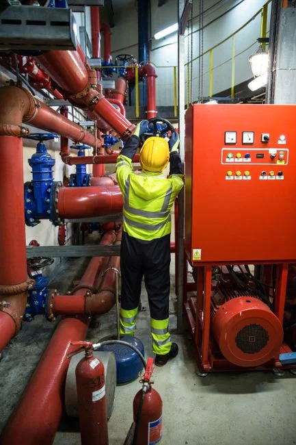
The reuse hierarchy should mirror the stream hierarchy: address the largest, most predictable stream first, then push down the contaminant ladder. Cooling-tower blowdown is the highest-leverage stream because the volume dominates (25–770 ML/yr per facility) and the chemistry is well characterised. Routing 60–80% of blowdown back to adiabatic or humidification make-up after softening and RO polish is the single most effective demand-reduction step available. UPW reject to scrubber feed or cooling make-up via RO followed by EDI polishing cuts municipal draw by 20–35%, and MBR-treated segregated sanitary covers mop water, landscape irrigation and toilet flushing.
The 2026 design point for a new Prague build is >70% total site water reuse even where the Water Act does not yet mandate it, because the §8 permit amendment under zákon 254/2001 Sb. will arrive inside the first permit cycle, and the CSRD ESRS E3 disclosure under FY 2026 will read more favourably against a >70% baseline than against a 50% reactive design.
CSRD ESRS E3 reports water withdrawal, discharge and intensity in m³ per revenue unit. The MBR aeration and the high-pressure RO pump drive 35–50% of OPEX (HydropureWater field data, 2026); RO membrane replacement at 3–5 years and biocide dosing for cooling make-up are the second-tier cost lines. Energy and water are therefore coupled at the disclosure level: a kilowatt-hour saved on RO is a cubic metre the disclosure can claim against a denominator that is audited.
For a 2026 benchmark, TSMC replaced 12% of its water with reclaimed in 2023, and the Phoenix reclaimed-water plant (groundbreaking Sept 2025, operational 2028) targets a cut from 4.75 M gal/day to 1.2 M gal/day (Verdict, 2025). Use TSMC as a benchmark, not as an exact target — a Prague back-end line will not match a leading-edge foundry's reuse fraction in 2026, but it should sit above the European data-hall median and track the >70% design point through the first permit cycle. For unit-operation sizing, see the cooling-tower blowdown engineering specs and ZLD cost breakdown and the chip fab water reuse recovery rates and ZLD decision framework references.
| Water line | Typical Prague baseline (m³/yr, 5 MW hall) | 2026 design reuse fraction | CSRD ESRS E3 line |
|---|---|---|---|
| Municipal draw — UPW feed | 35,000–60,000 | 20–35% cut via RO polish on reject | Water withdrawal |
| Cooling-tower make-up | 60,000–250,000 | 60–80% of blowdown to adiabatic make-up | Water withdrawal / consumption |
| Sanitary supply (potable) | 3,000–5,000 | ~90% via MBR reuse for toilet / irrigation | Water withdrawal |
| Discharge to PVK manhole | 15,000–40,000 | Concentrate + surplus sanitary only | Water discharge |
| Total site water reuse | — | >70% | Water intensity (m³ / revenue unit) |
2026 procurement checklist for a Prague site
Lock the headworks bar screen and the polishing RO skid first — their sizing constrains every downstream unit. Confirm the PVK discharge envelope against the actual mixed effluent at the manhole, and for segregated streams that are reused on site, verify the envelope at the brine line rather than at the building drain. Run a 12-month CSRD ESRS E3 water data baseline in parallel with commissioning, so the FY 2026 disclosure has auditable numbers rather than estimates. Plan a §8 permit amendment under zákon 254/2001 Sb. with the krajský úřad if the reuse fraction on any single stream exceeds ~50%, and submit the documentation packet (process flow, mass balance, sampling plan per vyhláška 428/2001 Sb.) at least 90 days before the target amendment date. For a parallel compliance walkthrough applied to a different basin, the Vancouver semiconductor and data-hall compliance guide covers the same four-stream logic against British Columbia and Metro Vancouver discharge limits and is a useful cross-check for the Prague documentation pack.
Frequently Asked Questions
What are the four segregated wastewater streams a 2026 Prague semiconductor or data-hall site must treat separately?
UPW reject and fab rinse, CMP/dicing and back-grind waste (back-end only), cooling-tower blowdown, and segregated sanitary effluent. Conflating them upstream is the most common reason operators miss the PVK trade-effluent envelope at the discharge manhole.
Which Czech law controls a semiconductor or data-hall discharge permit in Prague in 2026?
Zákon č. 254/2001 Sb. (the Water Act) sets the §8 discharge-permit framework, administered by the krajský úřad, and vyhláška č. 428/2001 Sb. governs wastewater sampling. PVK trade-effluent limits apply at the manhole on top of those instruments.
Does CSRD ESRS E3 require a Prague site to report water reuse in 2026?
Yes. From FY 2026, water withdrawal, discharge and intensity in m³ per revenue unit are reportable under CSRD ESRS E3, and the FY 2026 filing should be supported by at least 12 months of audited baseline data captured during commissioning.
What is the 2026 design-point reuse fraction for a new Prague build?
>70% total site water reuse, achieved by routing 60–80% of cooling-tower blowdown back to adiabatic make-up, cutting municipal draw by 20–35% on the UPW reject leg, and polishing segregated sanitary to reuse quality for toilet flushing and irrigation.