What Is a Constructed Wetland and How Does It Treat Wastewater
Constructed wetlands (CWs) are engineered treatment systems that use natural processes involving wetland vegetation, soils, and their associated microbial assemblages to improve water quality (per US EPA, epa.gov/wetlands/constructed-wetlands). They are not natural marshes repurposed for effluent duty; they are designed, lined, planted, and hydraulically controlled to deliver reproducible treatment performance. The first wastewater-focused experiments were carried out by Käthe Seidel at the Max Planck Institute in Plön, Germany, in the early 1950s, and the first fully constructed wetland — a free water surface (FWS) system — was built in the Netherlands in 1967 (per S3, Water journal, 2010).
Treatment in any CW configuration rests on three removal mechanisms working in parallel: microbial degradation of organic matter and ammonia in the biofilm attached to the substrate, adsorption and precipitation of dissolved species onto the media, and direct plant uptake of nutrients and metals. Plant uptake is the smallest contributor. Aboveground biomass typically sequesters less than 10% of the inflow nutrient load unless the vegetation is actively harvested at the end of each growing season (per Vymazal 2010, cited in S3). Designers should rely on the microbes and the substrate, not the plants, for the bulk load removal.
The Three Main Constructed Wetland Configurations
Three configuration families dominate the global installed base, and the choice between them is driven by influent strength and target effluent quality rather than by site aesthetics. Horizontal subsurface flow (HF), vertical subsurface flow (VF), and free water surface (FWS) systems differ in flow path, oxygen transfer, and treatment role within a plant flowsheet.
HF CWs consist of gravel or rock beds sealed by an impermeable layer and planted with emergent vegetation such as Phragmites or Typha; wastewater flows horizontally below the media surface, which keeps odour, mosquito, and public-access issues low (per S3). They are the workhorse for secondary sewage treatment and for wastewaters already diluted with stormwater. VF CWs dose influent intermittently across the top of the bed, pulling air into the media as the water percolates downward; this pulsed oxygen supply gives much better nitrification than HF beds, but the intermittent pumping raises O&M cost (per S3). FWS CWs are open-water cells with emergent vegetation rooted in sediment; they are the only configuration where long-term soil accretion occurs, because vegetation is not harvested (per S3). FWS systems are typically deployed for tertiary polishing where land is cheap and ammonia targets are modest.
| Parameter | HF (Horizontal Subsurface) | VF (Vertical Subsurface) | FWS (Free Water Surface) |
|---|---|---|---|
| Flow path | Horizontal, below media surface | Vertical, downward through media (or upflow in upflow variants) | Horizontal across open water |
| Oxygen transfer | Low (passive, ~0–5 g O₂/m²·d) | High (intermittent dosing draws air in) | Low–moderate (re aeration at surface) |
| Typical influent strength | Secondary, diluted with stormwater | Primary or secondary, higher BOD | Tertiary, low-strength |
| Placement in treatment train | Secondary | Primary or secondary | Tertiary polishing |
Design Parameters and Sizing a Constructed Wetland
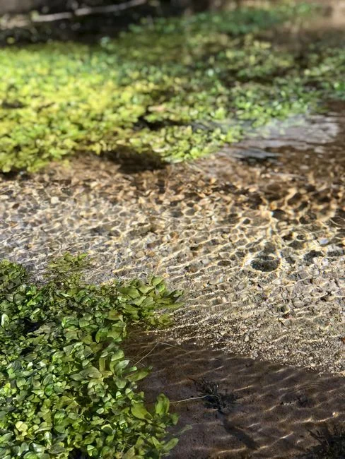
A defensible CW cell design rests on five numbers: hydraulic loading rate (HLR), biochemical oxygen demand (BOD) areal loading, media depth, aspect ratio, and the removal target by configuration. The envelopes below are consolidated from the Constructed Wetland Association database of more than 1,000 UK beds and the wider UK population of more than 1,200 systems, which collectively validate the parameter ranges against long-term operating data (per S5, Cooper 2008, Springer Netherlands).
| Design parameter | HF CW | VF CW | FWS CW |
|---|---|---|---|
| Hydraulic loading rate (m³/m²·d) | 0.02–0.06 | 0.03–0.08 (pulsed dosing) | 0.01–0.04 |
| BOD areal loading (g/m²·d) | 4–8 | 8–25 | 1–4 |
| Media depth (m) | 0.6–1.0 | 0.6–1.0 | 0.3–0.5 substrate + 0.2–0.4 free water |
| Aspect ratio (L:W) | 2:1 to 4:1 to limit short-circuiting | 1:1 to 2:1 acceptable; uniformity driven by dosing | 3:1 to 10:1 depending on plug-flow need |
| Typical BOD removal target (%) | 60–85 | 75–95 | 30–60 (polishing duty) |
| Typical NH₄-N removal target (%) | 20–50 (limited by low O₂) | 60–90 (aerobic bed) | 10–40 |
Layout details determine whether a CW cell performs to specifications. An impermeable liner — typically 1.0–1.5 mm HDPE — is mandatory for HF and VF beds to protect groundwater and force horizontal or vertical flow through the media. Inlet and outlet distribution must be engineered to spread flow across the full bed cross-section; a single inlet pipe on an HF cell will short-circuit 30–50% of the flow in the first 20% of the bed length. Cold-weather performance drops by 20–40% in HF and FWS systems once water temperature falls below 10 °C, and the standard mitigations are deeper media in HF and VF beds (toward the 1.0 m end of the range) or covered FWS cells.
Pretreatment and Effluent Polishing Around a Constructed Wetland
Industrial effluents from electroplating, dairy, landfill leachate, distillery, and aquaculture operations require upstream screening, grit removal, and frequently a dissolved air flotation (DAF) or equalization step to keep oil, grease, and suspended solids off the media. Untreated FOG will blind the top 10–20 cm of an HF or VF bed within a single operating season and destroy the hydraulic conductivity the design depends on. For high-FOG and high-suspended-solids industrial influents, a Dissolved Air Flotation (DAF) System sized for the peak hourly flow is the most cost-effective upstream guard. For high-strength wastewaters whose BOD exceeds the CW loading envelopes in the table above, a packaged biological reactor or MBR membrane bioreactor system upstream reduces the load to a level the CW can metabolize year-round.
Effluent polishing determines whether the water goes to surface discharge or to reuse. CW effluents carry residual COD, suspended solids, and fecal coliforms, and a disinfection step is normally required. For variable CW effluent quality, a chlorine dioxide generator delivers a stable residual across a wide flow and load range without forming the trihalomethanes associated with chlorination, and it tolerates the higher turbidity that a polishing-stage CW effluent can carry after storm events. Where reuse is the target, a UV sterilizer sized for the CW effluent's UV transmittance is the standard polish. The sizing logic for the DAF step is covered in detail in this Dissolved Air Flotation design parameters guide, and the MBR trade-offs versus conventional activated sludge for industrial streams are mapped in this MBR vs conventional activated sludge comparison.
Hybrid Constructed Wetland Systems for Industrial Effluents
Hybrid systems — VF in series with HF, VF in series with FWS, or VF and HF in parallel — are the default for municipal and industrial applications, and they have been documented for sewage, landfill leachate, slaughterhouse, shrimp and fish aquaculture, and winery wastewater (per S3). The hybrid concept works because each stage covers a different treatment objective: a VF stage handles nitrification and BOD oxidation under aerobic conditions, while a downstream HF or FWS stage completes denitrification and provides polishing for residual organics and suspended solids.
- Raw wastewater — flow equalization and coarse screening to remove rags and large debris.
- Primary solids and FOG removal — a Dissolved Air Flotation (DAF) System for industrial streams, or a primary clarifier for municipal sewage.
- Biological pretreatment — an MBR membrane bioreactor system for high-strength industrial flows that exceed the CW BOD loading envelope; otherwise the hybrid CW itself.
- Hybrid CW stage — VF in series with HF or FWS, sized to the loading table above.
- Polishing and reuse — ultrafiltration for reuse-quality water, followed by UV sterilizer or chlorine dioxide disinfection before discharge or reuse.
For industrial sites targeting near-reuse quality, pairing the hybrid CW with an ultrafiltration skid downstream removes the residual colloidal solids and pathogens that even a well-designed CW will leave behind, producing a permeate suitable for cooling-tower make-up, boiler feed pre-treatment, or process rinse water.
When a Constructed Wetland Is the Wrong Choice
Land availability is the primary constraint for CW implementation. Secondary sewage treatment in an HF or VF bed requires roughly 5–10 m² per population equivalent, so a 1,000 m³/d industrial site will need 5,000–25,000 m² of CW footprint depending on influent strength. On space-constrained brownfield sites or inside process buildings, mechanical treatment is the only realistic option.
Treatment performance is the second constraint. A single HF bed delivers limited nitrification because the bed is largely anaerobic inside the media; strict ammonia or total nitrogen limits normally require either mechanical aeration within the cell or a hybrid VF plus HF train. A standalone CW also cannot absorb toxic spikes: heavy metals, pH excursions below 5 or above 9, and solvent slugs will kill the biofilm and require months to recover, so any site with variable influent chemistry must install robust equalization and monitoring upstream. Finally, sites with prolonged freezing winters should plan for a 20–40% winter performance drop in HF and FWS systems, or budget for covered cells. Where any of these limits apply, a packaged mechanical plant, a membrane bioreactor, or an anaerobic digester followed by MBR — covered in this anaerobic digester maintenance guide — is the more defensible choice.
Frequently Asked Questions About Constructed Wetland Design
How much land does a constructed wetland need for municipal secondary treatment?
Approximately 5–10 m² per population equivalent for HF or VF beds in secondary duty, so a 1,000 m³/d plant serving roughly 5,000 people typically needs 25,000–50,000 m² of CW cell area (per S3, Water journal).
Which constructed wetland configuration gives the best ammonia removal?
Vertical subsurface flow (VF) systems, because intermittent surface dosing pulls oxygen into the media and supports nitrifying biofilm; expect 60–90% NH₄-N removal in a properly loaded VF bed (per S3).
What pretreatment does an industrial CW need upstream?
At minimum, screening and grit removal; for high-FOG or high-suspended-solids streams, a DAF unit is required to prevent media blinding, and for high-BOD streams exceeding 25 g BOD/m²·d an MBR or packaged biological reactor is needed upstream of the CW.
How does a constructed wetland perform in cold climates?
HF and FWS systems typically lose 20–40% of their BOD removal once water temperature falls below 10 °C; mitigations are deeper media (toward 1.0 m) for HF and VF beds, or
Frequently Asked Questions
What is the typical hydraulic loading rate for a horizontal subsurface flow constructed wetland?
The typical hydraulic loading rate (HLR) for horizontal subsurface flow (HSSF) constructed wetlands generally ranges from 0.02 to 0.10 meters per day (m/d). These rates are highly dependent on the hydraulic conductivity of the selected filter media, such as washed gravel or crushed rock, and the required retention time, which is typically designed for 5 to 10 days to ensure adequate pathogen removal and organic matter degradation.
How do VF and HF constructed wetlands differ in treatment performance?
Vertical Flow (VF) wetlands are characterized by intermittent loading, which promotes oxygen transfer and enhances nitrification, typically achieving effluent ammonia concentrations below 5 mg/L. In contrast, Horizontal Flow (HF) wetlands maintain saturated conditions, favoring denitrification and suspended solids removal, but provide limited aeration; consequently, VF systems are superior for nitrogen removal, while HF systems are more effective for total suspended solids (TSS) and anaerobic processes.
What influent BOD loading can a constructed wetland handle?
Constructed wetlands are typically designed for organic loading rates ranging from 20 to 100 kilograms of BOD5 per hectare per day (kg/ha/d). While systems can be pushed to higher loading rates during peak flows, exceeding 150 kg/ha/d often leads to surface clogging, anaerobic odors, and a significant reduction in dissolved oxygen levels within the bed, necessitating a larger surface area or multi-stage configurations for high-strength industrial wastewaters.
Do constructed wetlands work in cold climates?
Constructed wetlands remain functional in cold climates, though biological reaction rates follow an Arrhenius temperature dependency, typically requiring larger surface areas to compensate for reduced microbial activity during winter months. Engineering strategies such as increasing the media depth, utilizing surface mulch layers for insulation, or employing subsurface flow designs to protect the water column from freezing allow these systems to maintain compliance with discharge standards even in sub-zero ambient temperatures.
What pretreatment does a constructed wetland need for industrial wastewater?
Industrial wastewater pretreatment is critical to prevent clogging and protect the wetland media; standard requirements include primary clarification or septic tanks for solids removal, and oil-water separators for industrial effluents containing hydrocarbons. Depending on the specific pollutant profile, pH neutralization, heavy metal precipitation, and flow equalization tanks are often mandatory to keep influent concentrations within the range of 100 to 300 mg/L BOD to avoid system failure or toxic shock to the wetland vegetation.