
What Is a Nanofiltration Membrane and Why It Works for PFAS
A nanofiltration membrane for PFAS removal typically achieves 90–99% rejection of long-chain PFAS such as PFOA and PFOS while operating at substantially lower pressure than reverse osmosis. Rejection is driven by steric (size) exclusion and electrostatic repulsion between the negatively charged PFAS molecule and the membrane surface, which is why thin-film composite polyamide NF membranes (e.g. NF90, NF270) dominate industrial PFAS treatment trains.
NF occupies the middle of the pressure-driven membrane spectrum. Its nominal pore size sits at 0.5–2 nm with a molecular weight cut-off (MWCO) in the 200–1,000 Dalton range — loose enough to pass monovalent ions under low pressure, yet tight enough to retain most PFAS molecules. A PFOA molecule measures roughly 1.0–1.2 nm along its long axis; PFOS is slightly longer and bulkier. Because these hydrated dimensions approach the NF pore opening, steric exclusion alone can deliver substantial rejection even before charge effects are considered.
The second mechanism is electrostatic, sometimes called Donnan repulsion. At neutral pH, both the sulfonate or carboxylate head of a PFAS molecule and the carboxyl groups on a TFC polyamide surface carry negative charge. Like charges repel, and the PFAS ion is pushed back from the membrane interface. Together, the two mechanisms push long-chain PFAS rejection above 90% in well-operated systems. Ultrafiltration, with pore sizes an order of magnitude larger, has little to contribute; reverse osmosis, with a dense non-porous skin and 1.0–1.5 MPa operating pressure, achieves higher removal at the cost of substantially more energy. Among the four pressure-driven options (FO, RO, NF, UF), the 2026 review by S3/S4 in Journal of Water Process Engineering identifies NF as the best balance of removal efficiency and energy consumption — the position any design engineer should anchor to when defending an NF selection.
PFAS Removal Performance: What NF Actually Delivers
NF regularly exceeds 90% removal for the PFAS species that show up in industrial influents, with peak retentions of 99% reported under optimised conditions (S3/S4 review, 2026). That headline number, however, hides the chain-length dependence that drives every real design decision.
Long-chain PFAS — PFOA (C8), PFOS (C8), PFNA (C9) — are the easiest target. Their molecular weight and length push them well above the NF270/NF90 MWCO threshold, and their negative head group is fully ionised at typical wastewater pH. Rejection of 95–99% is routine on unmodified TFC polyamide elements, with the tighter NF90 and NFX products sitting at the upper end of that band.
Short-chain PFAS — PFBA (C4), PFPeA (C5), PFBS (C4) — are the engineering caveat that the academic literature understates. Their smaller hydrated radius drops them close to the NF pore window, and their higher water solubility means they have less thermodynamic incentive to be rejected. Unmodified TFC polyamide NF typically retains 50–80% of these species, which is rarely enough on its own to meet a 10 ng/L discharge target. The S3/S4 review flags short-chain retention as the open challenge for the technology.
The four benchmark membranes tested at 2×10⁻⁶ mol/L feed in that review — NF270, NF90, NFX, and DK — split cleanly into two camps. NF90 and NFX are the tighter, higher-rejection variants with higher salt rejection; NF270 is the higher-flux, lower-rejection option. The DK membrane sits between them depending on the species. None of the four is sufficient as a stand-alone barrier for short-chain PFAS in a tight regulatory envelope.
Feedwater concentration matters as much as membrane chemistry. Groundwater PFAS typically runs 20–20,000 ng/L; landfill leachate has been measured at 214,000 ng/L — roughly ten times higher (S3/S4 review, 2026). Leachate is the worst-case industrial matrix for any barrier technology: high TDS, high organic matter, high scaling potential, and PFAS concentrations that push concentrate management to the front of the design problem. In that envelope NF is almost always paired with GAC polishing or downstream RO rather than specified alone.
| Membrane | Class | Long-chain PFAS (PFOA/PFOS) | Short-chain PFAS (PFBA/PFBS) | Best-fit application |
|---|---|---|---|---|
| NF270 | Loose NF, high flux | 90–95% | 40–60% | High-throughput industrial water with low regulatory threshold on C4–C5 species |
| NF90 | Tight NF | 95–99% | 60–80% | Long-chain-dominated leachate polishing, pre-RO for potable reuse |
| NFX | Tight NF | 95–99% | 65–80% | Hybrid NF + GAC trains targeting <10 ng/L |
| DK | Intermediate | 92–97% | 50–70% | Multi-barrier systems balancing flux and rejection |
NF vs RO vs UF vs GAC vs Ion Exchange: Choosing the Right Barrier

No single technology wins across every PFAS species and every feed matrix. The right answer for an industrial wastewater train depends on the chain-length distribution of the influent, the OPEX budget, and what happens to the concentrate stream. The matrix below is what a design engineer can defend in a P&ID review or a design basis memo.
RO delivers more than 99% PFAS rejection across the full chain-length spectrum, but it does so at 1.0–1.5 MPa feed pressure and 0.7–1.5 kWh/m³ specific energy (S3/S4 review, 2026). NF runs at 0.3–1.0 MPa and roughly half the specific energy, and still clears 90–99% on long-chain species — the compromise most industrial plants land on. UF is the cheapest to operate but offers almost no PFAS removal on its own; its real role is upstream of NF or RO as a particulate and colloid barrier. GAC is effective for long-chain PFAS in low-organic water and is the workhorse of many drinking-water plants, but it is single-use, fouled by landfill leachate organics, and not regenerable for PFAS in any practical sense. Ion exchange resins deliver higher capacity and faster kinetics than GAC, but they regenerate into a brine that concentrates the PFAS mass and creates its own disposal problem.
Conventional coagulation–flocculation–sedimentation is not a PFAS barrier. The S3/S4 review cites a study in which conventional water treatment increased PFOA by 61% and PFOS by 18% in the finished water — a useful data point for any engineer being pushed to specify low-cost pretreatment as a "polish."
Specifying rule of thumb: choose NF when the design target is more than 90% long-chain PFAS rejection, the feed TDS is low to moderate (under about 5,000 mg/L), and the energy budget cannot support RO-grade operation. Choose RO when short-chain PFAS, GenX (HFPO-DA), or other fluoride-substituted ether species dominate the analyte list, or when the discharge limit is at or below 10 ng/L for individual species. For an industrial reverse osmosis polishing stage on NF concentrate, the cost stack usually makes more sense than trying to push a single NF stage tighter. Spiral-wound membrane elements and pressure vessels for either barrier are interchangeable at the vessel level, which simplifies spares.
| Technology | Removal mechanism | PFAS rejection | Operating pressure | Regenerable? | Concentrate handling | Typical industrial feed |
|---|---|---|---|---|---|---|
| NF (TFC polyamide) | Steric + Donnan | 90–99% long-chain; 50–80% short-chain | 0.3–1.0 MPa | No (cleaning only) | 5–20× feed PFAS mass; RO or thermal | Landfill leachate, plating rinse, textile effluent |
| RO (TFC polyamide) | Solution-diffusion + Donnan | >99% across chain lengths | 1.0–1.5 MPa | No (cleaning only) | 10–30× feed PFAS; thermal destruction preferred | High-purity reuse, short-chain-dominated feeds |
| UF | Size exclusion (large pores) | <20% on its own | 0.05–0.3 MPa | No | None generated for PFAS | Pretreatment for NF/RO, not a stand-alone PFAS barrier |
| GAC | Adsorption | >90% long-chain; poor on short-chain | Atmospheric | No (single-use for PFAS) | Spent carbon to thermal destruction | Drinking water, low-organic industrial water |
| Ion exchange | Electrostatic exchange | >90% long- and mid-chain | Atmospheric | Yes (brine regeneration) | Regeneration brine; small volume, high PFAS | Drinking water, semiconductor reclaim |
Key Membrane and Operating Parameters Engineers Must Specify
A defensible NF datasheet query covers eight non-negotiable items. MWCO and nominal pore size (0.5–2 nm) set the steric exclusion envelope. Membrane chemistry — TFC polyamide versus sulfonated polyethersulfone — drives chlorine tolerance, surface charge, and cleanability. Zeta potential at pH 7 quantifies the negative surface charge that drives Donnan repulsion. Salt rejection data for NaCl (typically 40–70% on NF270, 85–95% on NF90) and MgSO₄ (typically 95–99% on NF270, 99%+ on NF90) are the proxy most vendors publish for membrane tightness. Pure water flux, in LMH at a stated pressure, and spacer geometry — 31 mil for fouling-prone feeds, 46 mil for cleaner water and higher recovery — round out the spec.
The operating window for spiral-wound NF is well defined. Feed pressure runs 0.3–1.0 MPa, recovery 50–85% per stage, cross-flow velocity 10–30 cm/s, pH 6.5–8.5 for stable polyamide chemistry, and a temperature ceiling of 35–45°C depending on element. Push past the temperature limit and the polyamide layer hydrolyses; drop below pH 6 and amide bond cleavage accelerates; exceed 85% recovery and concentration polarisation starts to dominate flux loss.
Feedwater limits drive pretreatment. SDI₁₅ below 5 is the standard spiral-wound ceiling. Free chlorine above 0.1 mg/L will oxidise the polyamide; a sodium metabisulphite dosing system ahead of the cartridge filter is the usual fix. Hardness must be managed — NF90-class membranes reject divalent ions efficiently, which is the engineering point, but also concentrate them on the reject side and scale quickly without antiscalant or softening. A small RO polish on the NF concentrate is a common way to recover both water and the scaling ions before discharge.
The flux-versus-rejection trade-off is qualitative, not a single curve. Tighter membranes (NF90, NFX) reject more PFAS and more salt, but produce less permeate per unit membrane area at a given pressure. Looser membranes (NF270) give higher flux at the cost of lower rejection, especially on short-chain species. Vendor curves understate long-term fouling; pilot data on the actual site water, run for at least four to six weeks, is the only way to anchor a real number.
| Parameter | NF270 (loose) | NF90 (tight) | NFX (tight) |
|---|---|---|---|
| MWCO (Da) | ~300–400 | ~200 | ~200–300 |
| NaCl rejection | 40–60% | 85–95% | 70–85% |
| MgSO₄ rejection | 95–98% | 99%+ | 98–99% |
| Pure water flux (LMH @ 25°C, 0.5 MPa) | 12–18 | 6–10 | 8–12 |
| Surface charge at pH 7 | Negative (moderate) | Negative (strong) | Negative (strong) |
| Spacer geometry (typical) | 31 or 46 mil | 31 mil | 31 or 46 mil |
| Long-chain PFAS rejection | 90–95% | 95–99% | 95–99% |
Designing an NF System for Industrial PFAS Wastewater
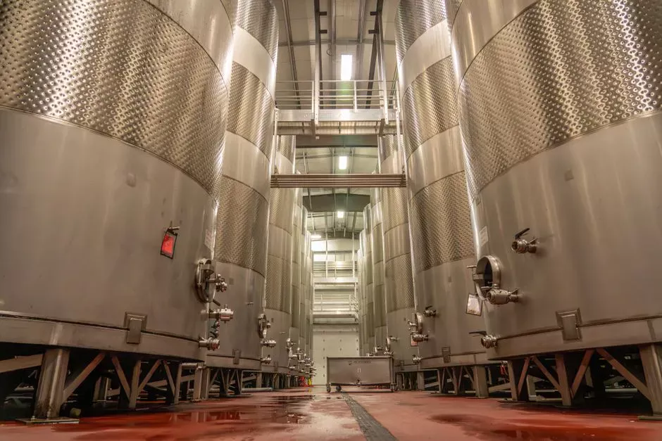
A working industrial NF train runs in the order equalisation → pretreatment → NF → concentrate management. Equalisation dampens flow and load swings; for high-strength feeds an MBR upstream of NF for high-strength industrial feeds can drop COD and TSS by an order of magnitude before the membrane sees the water. Pretreatment is the difference between a clean six-month run and a thirty-day wash cycle: a multi-media filter for NF feed conditioning handles turbidity and iron, followed by UF pretreatment ahead of the NF array if SDI₁₅ is above 3 or organic loading is variable. Antiscalant dosing on the NF feed is standard for any feed with hardness above about 200 mg/L as CaCO₃.
For flows above about 50 m³/h, a two-stage NF array with 65–80% overall recovery and 4×2 multi-element vessels is the layout that consistently delivers the lowest specific energy. The first stage takes the feed and rejects the bulk; the second stage treats the first-stage concentrate at lower flux to recover additional permeate and reduce the volume sent to concentrate management. The S3/S4 review makes the point cleanly: membrane performance depends on feedwater matrix, and organic-matter fouling degrades long-term rejection — the design that ignores pretreatment pays for it in the second year of operation.
Concentrate handling is the line item that decides whether an NF project is approved. NF concentrate carries 5–20× the feed PFAS mass in 15–35% of the feed volume. It cannot be discharged without a further barrier. The three common routes are: an industrial reverse osmosis polishing stage that recovers 80–90% of the concentrate as reusable water and sends the RO reject to thermal destruction; evaporation followed by crystallisation or solidification for landfill; or direct incineration of the liquid concentrate in a hazardous-waste facility. For a hybrid membrane process design for trace contaminants in higher-strength matrices, the same architecture scales; the article on wafer-fab arsenic process design walks through the concentrate handling logic in more detail. Phosphate and hardness management for NF pretreatment is also worth reading for plants with elevated scaling potential.
Frequently Asked Questions
Can nanofiltration remove short-chain PFAS like PFBA and PFBS?
Unmodified TFC polyamide NF typically retains 50–80% of PFBA and PFBS on its own, which is rarely enough to meet a 10 ng/L discharge target (S3/S4 review, 2026). For tight regulatory limits on C4–C5 species, specify RO instead, or pair NF with a downstream GAC or ion-exchange polish.
What operating pressure does an NF system need for PFAS removal?
Industrial spiral-wound NF for PFAS runs at 0.3–1.0 MPa feed pressure, roughly half the energy of an RO system at 1.0–1.5 MPa. Recovery per stage is set between 50% and 85% to balance flux against concentration polarisation.
How is NF concentrate handled when it contains concentrated PFAS?
NF concentrate carries 5–20× the feed PFAS mass in 15–35% of the feed volume. Standard handling routes are an RO polish of the NF retentate followed by thermal destruction of the RO reject, evaporation with crystallisation, or direct liquid injection into a hazardous-waste incinerator.
Why is landfill leachate the hardest PFAS feed for any barrier technology?
Landfill leachate combines very high PFAS concentrations (up to 214,000 ng/L), high TDS, high organic matter, and scaling potential, all in one feed (S3/S4 review, 2026). The organic load fouls both membranes and GAC, so leachate trains almost always pair NF with a downstream GAC, ion exchange, or RO polish to meet discharge limits.