Why Arsenic Wastewater Treatment is Critical for Semiconductor Fabs
Compliance with arsenic discharge standards is a non-negotiable operational requirement for semiconductor fabs, as EPA POTW limits frequently mandate effluent concentrations below 10 µg/L. For facilities manufacturing Gallium Arsenide (GaAs) or Silicon Carbide (SiC) wafers, arsenic wastewater is a primary byproduct of etching, grinding, and thinning processes. Typical influent arsenic concentrations in these fabs range from 50 mg/L to 500 mg/L (per Top 3 study), necessitating a removal efficiency of 99.9% or higher to meet regulatory thresholds. Failure to maintain these levels carries severe financial and operational risks; U.S. EPA 2024 enforcement data indicates that penalties for non-compliance range from $50,000 to $250,000 per violation, often accompanied by mandatory production shutdowns until remediation is verified.
Global regulatory landscapes are tightening significantly. While the China GB 31573-2015 standard currently sets a limit of <50 µg/L for industrial discharge, the 2025 update is expected to align with international benchmarks at <10 µg/L. Beyond legal penalties, arsenic poses a catastrophic risk to aquatic ecosystems due to its high bioaccumulation potential and carcinogenicity. Publicly Owned Treatment Works (POTWs) increasingly reject untreated or poorly treated effluent from fabs to prevent the inhibition of biological treatment stages and to avoid the contamination of municipal biosolids. For EHS managers, implementing a robust treatment system is not merely a utility requirement but a core component of "license to operate" risk management.
Arsenic Chemistry in Wafer Fab Wastewater: Forms, Solubility, and Removal Challenges
Arsenic in wafer fab wastewater primarily exists in two oxidation states, where trivalent arsenite [As(III)] exhibits 60 times the toxicity of pentavalent arsenate [As(V)] and significantly higher solubility. As(III) typically exists as uncharged arsenious acid (H₃AsO₃) at neutral pH, making it exceptionally difficult to remove via standard precipitation or ion exchange. In contrast, As(V) exists as negatively charged ions (H₂AsO₄⁻ or HAsO₄²⁻), which are more reactive with coagulants. Success in arsenic removal depends entirely on the successful conversion of As(III) to As(V) before the precipitation stage.
The presence of co-contaminants further complicates the removal process. GaAs fab effluent often contains gallium (approx. 20 mg/L), indium (5 mg/L), and fluoride (100–500 mg/L). Fluoride, in particular, competes with arsenic for adsorption sites and can interfere with the formation of ferric arsenate precipitates. standard filtration technologies like reverse osmosis often fail as a primary treatment because arsenic rejection rates for As(III) are typically <90%, according to Top 5 review data. This necessitates a sophisticated chemical pretreatment sequence to stabilize the arsenic into a solid phase.
| Parameter | Arsenite [As(III)] | Arsenate [As(V)] |
|---|---|---|
| Chemical Form (pH 6-8) | H₃AsO₃ (Neutral) | H₂AsO₄⁻ / HAsO₄²⁻ (Anionic) |
| Toxicity Level | 60x Higher than As(V) | Baseline Toxicity |
| Removal Ease | Difficult (Requires Oxidation) | Moderate (Precipitation) |
| Solubility in Water | High (10-15 g/L) | Lower (pH dependent) |
| Best Precipitant | N/A (Must be oxidized first) | Ferric Sulfate / Slaked Lime |
Hybrid Process Design: Step-by-Step Engineering Specs for 99.99% Arsenic Removal
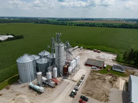
Achieving 99.99% arsenic removal requires a multi-stage hybrid process that integrates chemical oxidation, co-precipitation, and tertiary adsorption to reach sub-10 µg/L levels. This process begins with Stage 1: Oxidation. Potassium permanganate (KMnO₄) is the preferred oxidant, dosed at a ratio of 1.5–2.5 mg/L per mg of As(III) present. This ensures the complete conversion of arsenite to arsenate within a reaction time of 10–15 minutes. PLC-controlled chemical dosing systems for precise arsenic treatment are essential here to prevent oxidant under-dosing (which leaves soluble arsenic) or over-dosing (which can color the effluent).
Stage 2: Precipitation involves the addition of ferric sulfate (Fe₂(SO₄)₃) at a dosing ratio of 10–20 mg/L per mg of As(V). The pH must be strictly maintained between 6.0 and 8.0 using slaked lime (Ca(OH)₂). In this range, arsenic ions co-precipitate with ferric hydroxide to form stable ferric arsenate [FeAsO₄]. A hydraulic retention time (HRT) of 30–60 minutes is required to allow for complete floc formation. Stage 3: Adsorption serves as the polishing step, using a 1:1 mixture of bentonite and activated carbon at a dosage of 0.5–1.0 g/L. This stage captures residual arsenic and organic complexes, with a contact time of 20–30 minutes.
| Process Stage | Chemical Agent | Dosing Ratio / Concentration | Retention Time |
|---|---|---|---|
| Oxidation | KMnO₄ | 1.5–2.5 mg per mg As(III) | 10–15 Minutes |
| Precipitation | Fe₂(SO₄)₃ + Ca(OH)₂ | 10–20 mg per mg As(V) @ pH 6-8 | 30–60 Minutes |
| Adsorption | Bentonite + AC | 0.5–1.0 g/L | 20–30 Minutes |
| Flocculation | Anionic PAM | 1–3 mg/L | 5–10 Minutes |
Sludge management is the final critical engineering consideration. Ferric arsenate sludge is classified as hazardous waste (EPA RCRA D004). To reduce disposal costs and environmental liability, the sludge must be stabilized using a 10-15% cement or lime mixture before being processed through hazardous sludge dewatering systems for arsenic waste. Modern systems utilize ORP sensors to automate oxidation and online arsenic analyzers to provide real-time effluent verification, ensuring that any process drift is corrected before a discharge violation occurs.
Emerging Technologies: SPIONs, Membrane Filtration, and Electrocoagulation for Arsenic Removal
Emerging technologies such as superparamagnetic iron oxide nanoparticles (SPIONs) and electrocoagulation provide alternative pathways for arsenic removal with reduced chemical footprints compared to traditional lime softening. SPIONs represent the frontier of high-efficiency treatment, capable of achieving >99% removal at dosages as low as 0.1–0.5 g/L. These nanoparticles offer a massive surface-area-to-volume ratio, allowing for rapid kinetics (15-minute contact time) and the ability to reduce 100 mg/L influent to <5 µg/L. However, the capital cost remains high ($500–$1,200/m³ treated), and the regeneration of nanoparticles requires specialized magnetic separation equipment.
Membrane filtration, specifically the combination of Ultrafiltration (UF) and Nanofiltration (NF), can achieve 98-99% removal of pentavalent arsenic. This setup is often used as a final polishing stage following precipitation. To prevent rapid fouling from the high mineral content of fab wastewater, high-rejection RO systems for arsenic polishing require extensive pretreatment, including multi-media filtration and antiscalant dosing. Electrocoagulation is another viable alternative, generating Fe³⁺ ions in-situ via sacrificial iron electrodes. This method reduces chemical handling and can lower chemical costs by 30-50%, though it requires significant energy consumption (approx. 0.5–2.0 kWh/m³) and regular electrode replacement.
| Technology | Footprint | Removal Efficiency | Primary Advantage |
|---|---|---|---|
| Precipitation | Large | 99.9% | Lowest OPEX / Proven reliability |
| SPIONs | Smallest | >99.99% | Ultra-low effluent levels |
| Membranes (NF/RO) | Medium | 99.0% | Simultaneous multi-ion removal |
| Electrocoagulation | Medium | 98.5% | No bulk chemical storage |
Cost Breakdown: CAPEX, OPEX, and ROI for Wafer Fab Arsenic Treatment Systems
The total cost of ownership for an arsenic treatment system in a semiconductor environment is driven by hazardous sludge disposal fees, which can account for up to 40% of annual OPEX. For a standard precipitation and adsorption system (50–500 m³/day), CAPEX typically ranges from $300 to $800 per m³ of daily capacity. In contrast, advanced SPIONs systems can reach $1,500/m³ due to the complexity of the magnetic recovery units. However, the higher CAPEX of advanced systems can sometimes be offset by lower sludge volumes, as traditional lime precipitation generates significant secondary waste.
Operational expenses (OPEX) are subdivided into chemicals, energy, and waste management. Chemical costs for ferric sulfate and lime are relatively low ($0.10–$0.30/m³), but hazardous waste disposal fees for arsenic-laden sludge range from $0.20 to $0.50/m³ depending on local landfill regulations. Fabs can improve ROI by integrating hazardous sludge dewatering systems for arsenic waste to reach 20-30% solids concentration, significantly reducing the weight of waste hauled off-site. Additionally, PLC-controlled chemical dosing systems for precise arsenic treatment can reduce chemical waste by 30%, preventing the "over-dosing" common in manual operations.
| Fab Capacity | System Type | Est. CAPEX | Est. OPEX (per m³) | Payback Period |
|---|---|---|---|---|
| 50 m³/day | Batch Precipitation | $45,000 | $1.10 | 18 Months* |
| 200 m³/day | Continuous Hybrid | $140,000 | $0.85 | 14 Months* |
| 500 m³/day | Hybrid + RO Polish | $420,000 | $0.75 | 12 Months* |
*Payback period calculated based on avoidance of $100k/year average compliance penalties and reduced water discharge surcharges.
Compliance and Validation: Meeting Global Discharge Standards for Arsenic
Validation of arsenic removal systems requires high-precision analytical methods like Inductively Coupled Plasma Mass Spectrometry (ICP-MS) to ensure compliance with tightening global standards. While many fabs historically targeted a 50 µg/L limit, current best practices and regional mandates in Taiwan and the EU are pushing targets toward <5 µg/L. Achieving these levels consistently requires a rigorous validation protocol, including 24-hour composite sampling and strict chain-of-custody documentation for third-party lab audits. Real-time data logging of pH and ORP levels is now a standard requirement for environmental audits to prove process stability.
Common compliance pitfalls include "arsenic slip" caused by incomplete oxidation of As(III) or pH drift. If the pH falls below 6.0, the solubility of ferric arsenate increases sharply; if it rises above 8.5, the precipitates can begin to redissolve. EHS managers must also ensure that sludge stabilization is verified through Toxicity Characteristic Leaching Procedure (TCLP) testing before the waste leaves the site. For fabs looking to streamline their environmental footprint, exploring zero liquid discharge (ZLD) solutions for semiconductor fabs can provide a pathway to bypass discharge limits entirely by recycling treated water back into the facility.
| Region/Standard | Arsenic Limit (µg/L) | Primary Monitoring Method |
|---|---|---|
| U.S. EPA POTW | <10 | ICP-MS or GFAA |
| China GB 31573-2015 | <50 (2025: <10) | Atomic Fluorescence |
| Taiwan EPA | <5 | ICP-MS |
| EU Industrial Emissions | <10 | ICP-MS |
Case Study: 99.99% Arsenic Removal in a 200 mm GaAs Fab

A 200 mm GaAs wafer manufacturing facility successfully reduced influent arsenic concentrations from 120 mg/L to <5 µg/L using a precision-dosed hybrid precipitation system. The facility processed 150 m³/day of wastewater characterized by high arsenic loads and significant gallium co-contamination. Prior to the upgrade, the fab struggled with inconsistent effluent quality due to manual chemical dosing and poor oxidation control. The new system implemented a three-stage sequence: KMnO₄ oxidation (2.0 mg/L dose), followed by ferric sulfate precipitation at pH 7.2, and a final bentonite/activated carbon adsorption stage.
The results were immediate: effluent arsenic levels dropped to a consistent 4.2 µg/L, representing a 99.996% removal efficiency. By integrating a hazardous sludge dewatering systems for arsenic waste, the fab reduced its daily sludge volume to 0.8 m³ at 20% solids, cutting disposal costs by 45%. The total chemical cost was optimized to $0.22/m³. A key lesson learned during the pilot phase was that pH drift to 5.5—caused by an upstream process dump—temporarily reduced removal efficiency to 99.8%. This led to the installation of redundant, automated pH control loops and an online arsenic analyzer to provide an automated shut-off valve for the discharge line, ensuring 100% compliance during process upsets.
How to Select the Right Arsenic Treatment System for Your Wafer Fab
Selecting an arsenic treatment system involves a multi-variable analysis of influent chemistry, available footprint, and the specific discharge permit requirements of the local municipality. For small-scale operations or R&D fabs with <50 m³/day of wastewater, batch treatment systems provide the most cost-effective solution. For high-volume production fabs (>500 m³/day), continuous hybrid systems with integrated membrane polishing are often necessary to meet the stringent <5 µg/L limits while managing high flow rates. Fabs dealing with complex mixtures should also consider gallium recovery from semiconductor wastewater to offset treatment costs.
When evaluating vendors, procurement teams should prioritize systems that offer high levels of automation. PLC-controlled chemical dosing systems for precise arsenic treatment reduce labor costs and eliminate the human error that leads to compliance excursions. if the fab is located in a water-stressed region, the system should be compatible with high-rejection RO systems for arsenic polishing to enable water reuse. Always request pilot test data using your specific wastewater matrix, as the presence of fluoride or surfactants can significantly alter the performance of standard chemical recipes.
| Selection Factor | Precipitation/Adsorption | SPIONs / Nano-Tech | Membrane/RO Systems |
|---|---|---|---|
| Best For | General GaAs Fabs | Space-Constrained Fabs | Water Reuse/ZLD Goals |
| Inlet As Conc. | Up to 500 mg/L | Up to 100 mg/L | <10 mg/L (as polish) |
| Sludge Volume | High | Low | None (Liquid Brine) |
| Complexity | Low-Medium | High | Medium-High |
Frequently Asked Questions
Why can't I use standard pH adjustment to remove arsenic?Standard pH adjustment alone is insufficient because arsenic solubility does not follow a simple U-curve like metals such as copper or nickel. Arsenic must be in the pentavalent [As(V)] state to react effectively with iron or calcium salts. Even then, without a coagulant like ferric sulfate, the resulting precipitates are often too fine to settle effectively, leading to "pin-floc" carryover and discharge violations. A hybrid approach of oxidation, precipitation, and adsorption is required to reach the <10 µg/L levels mandated for semiconductor fabs.
How do I handle the sludge generated from arsenic treatment?Arsenic-laden sludge is a hazardous waste (RCRA D004) and must be handled with strict compliance. The best practice is to dewater the sludge using a filter press to reduce volume and weight, then stabilize it with lime or cement to pass TCLP testing. For facilities looking to reduce their environmental liability, exploring chromium wastewater treatment solutions for semiconductor fabs can provide insights into managing similar heavy metal waste streams.
What is the most common cause of arsenic treatment system failure?The most common failure point is incomplete oxidation of As(III). If the ORP (Oxidation-Reduction Potential) is not maintained at the correct level, arsenite will remain in solution and pass through the precipitation stage entirely. Secondarily, poor pH control—specifically allowing the pH to drift above 8.5—will cause ferric arsenate to redissolve. Automated dosing and continuous monitoring are the only reliable ways to prevent these failures in a high-volume manufacturing environment.