Why Chromium in Wafer Fabs Is a Regulatory and Operational Nightmare
Wafer fab chromium wastewater treatment in 2025 demands a sophisticated approach, moving beyond basic compliance to robust operational efficiency. Hexavalent chromium (Cr⁶⁺), a byproduct of photoresist stripping, etching, and CMP processes, typically appears in semiconductor wastewater at concentrations ranging from 10–100 mg/L (per EPA 2024 semiconductor wastewater benchmarks). The strict regulatory environment, exemplified by China’s GB 8978-1996 (<0.5 mg/L total chromium) and the EU’s Industrial Emissions Directive (<0.2 mg/L Cr⁶⁺), necessitates advanced treatment to avoid severe penalties. Non-compliance with U.S. EPA standards for Publicly Owned Treatment Works (POTWs) can incur fines up to $50,000 per day under the Clean Water Act. A stark reminder of these risks occurred in 2023 when a 5 nm fab in Taiwan faced a 6-month compliance overhaul after chromium discharge violations, resulting in $3.2 million in penalties and emergency retrofits. Beyond regulatory burdens, chromium poses significant operational hazards. Cr⁶⁺ is highly corrosive to standard 316L stainless steel piping at concentrations exceeding 50 mg/L, leading to leaks, equipment failures, and costly unplanned downtime, which SEMI 2024 fab cost reports estimate at an average of $1.8 million per incident. In water-scarce regions like Taiwan and Arizona, where water reuse is paramount, effective chromium removal is not just about compliance but also about securing essential operational resources and mitigating escalating costs.
Chromium Chemistry in Wafer Fab Wastewater: From Hexavalent to Harmless
Understanding the fundamental chemistry of chromium is critical for designing an effective wafer fab wastewater treatment system. The primary challenge lies in the extreme toxicity and mobility of hexavalent chromium (Cr⁶⁺), which must be converted into a less harmful, precipitable form, trivalent chromium (Cr³⁺). Cr⁶⁺ is highly soluble and poses significant environmental and health risks, while Cr³⁺, under the right conditions, can be readily removed as insoluble chromium hydroxide, Cr(OH)₃. The cornerstone of this transformation is chemical reduction. The key reaction involves reducing Cr⁶⁺ to Cr³⁺ using a reducing agent, typically sodium metabisulfite (Na₂S₂O₅). This process is highly pH-dependent, with optimal reduction occurring in a strongly acidic environment between pH 2 and 3, as defined by ASTM D1687-21. The reaction is represented as: Cr₂O₇²⁻ + 3HSO₃⁻ + 5H⁺ → 2Cr³⁺ + 3SO₄²⁻ + 4H₂O. For efficient reduction, sodium metabisulfite is dosed at approximately 3–5 mg per mg of Cr⁶⁺. Real-time monitoring of the oxidation-reduction potential (ORP) is essential to confirm complete reduction, with target ranges typically between -300 and -500 mV. Following reduction, the wastewater is subjected to precipitation. Cr³⁺ is precipitated as Cr(OH)₃ by raising the pH to between 8 and 9, a range commonly cited in EPA guidelines (e.g., EPA 832-F-00-018). Alkaline agents like lime (Ca(OH)₂) or sodium hydroxide (NaOH) are used for this purpose. The precipitation reaction is: Cr³⁺ + 3OH⁻ → Cr(OH)₃↓. Precise pH control during both reduction and precipitation is non-negotiable for achieving high removal efficiencies and preventing the carryover of residual chromium species.
| Parameter | Cr⁶⁺ Reduction | Cr³⁺ Precipitation |
|---|---|---|
| Target pH Range | 2–3 | 8–9 |
| Primary Chemical Agent | Sodium Metabisulfite (Na₂S₂O₅) | Lime (Ca(OH)₂) or Sodium Hydroxide (NaOH) |
| Required Dosing (per mg Cr⁶⁺) | 3–5 mg Na₂S₂O₅ | Stoichiometric + excess for pH adjustment |
| Key Monitoring Indicator | ORP (-300 to -500 mV) | pH |
| Resulting Chromium Species | Cr³⁺ (soluble) | Cr(OH)₃ (insoluble precipitate) |
Hybrid Process Design for 99.9% Chromium Removal: Step-by-Step Engineering Blueprint
Achieving the stringent 99.9% chromium removal required for modern wafer fab wastewater compliance and reuse necessitates a multi-stage hybrid process. This blueprint integrates chemical treatment with advanced physical separation technologies. The process begins with Step 1: Equalization, typically involving a 316L stainless steel tank with a 4–6 hour retention time. This stage is crucial for homogenizing influent chromium concentrations, which can fluctuate significantly from 10–100 mg/L Cr⁶⁺, ensuring consistent downstream treatment performance. Next is Step 2: Reduction. The wastewater’s pH is lowered to 2–3 using sulfuric acid (H₂SO₄), followed by the precise dosing of sodium metabisulfite (3–5 mg/mg Cr⁶⁺) via an automatic chemical dosing system. A reaction time of 30–60 minutes is standard, with an ORP probe continuously monitoring to ensure the reduction target of -300 to -500 mV is met. Following reduction, Step 3: Precipitation occurs. The pH is raised to 8–9 using lime (Ca(OH)₂) or NaOH to precipitate Cr³⁺ as Cr(OH)₃. A flocculant, such as polyacrylamide (1–3 mg/L), is added to enhance the aggregation of precipitated solids, facilitating efficient settling in a lamella clarifier designed with a surface loading rate of 20–40 m/h, requiring a settling time of 2–4 hours. For bulk removal of chromium hydroxide sludge, a high-efficiency DAF system for chromium hydroxide sludge separation can be integrated here. The fourth stage is Step 4: Filtration, a dual-stage process. A multimedia filter (sand/anthracite) removes suspended solids (TSS), followed by a tertiary polishing step. This can be either ultrafiltration (UF) using 0.02 μm PVDF membranes for chromium polishing in ZLD systems or an ion exchange column employing a strong base anion resin. UF systems typically achieve a 90–95% recovery rate. Finally, Step 5: Sludge Dewatering is performed using an automated filter press for chromium sludge dewatering to 30% solids, such as a plate-and-frame filter press with a filtration area of 10–50 m², to significantly reduce sludge volume and associated disposal costs. Common failure modes include incomplete reduction due to ORP probe drift, which is mitigated by weekly calibration, and UF membrane fouling from organic carryover, resolved with regular clean-in-place (CIP) cycles. For systems aiming for Zero Liquid Discharge (ZLD), a subsequent Reverse Osmosis (RO) stage would follow UF for further water recovery.
| Process Step | Primary Function | Key Equipment | Typical Parameters | Performance Goal |
|---|---|---|---|---|
| Equalization | Homogenize flow & concentration | 316L Stainless Steel Tank | 4–6 hr retention | Stable influent |
| Reduction | Cr⁶⁺ → Cr³⁺ | Reactor, H₂SO₄ dosing, Na₂S₂O₅ dosing, ORP probe | pH 2–3, ORP -300 to -500 mV, 30–60 min reaction | >99% Cr⁶⁺ converted |
| Precipitation | Cr³⁺ → Cr(OH)₃↓ | Reactor, Ca(OH)₂/NaOH dosing, Flocculant dosing, Lamella Clarifier | pH 8–9, 2–4 hr settling | Efficient solid-liquid separation |
| Filtration (Pre-polishing) | TSS Removal | Multimedia Filter | Influent TSS < 50 mg/L | Effluent TSS < 5 mg/L |
| Filtration (Polishing) | Residual Cr³⁺/Dissolved Cr Removal | UF Membranes (0.02 μm) or Ion Exchange Resin | UF: 0.02 μm pore size; IX: Anion resin | Effluent Cr < 0.1 mg/L |
| Sludge Dewatering | Volume Reduction | Plate-and-Frame Filter Press | Target solids: 20–30% | Reduced disposal volume |
Treatment Method Comparison: Reduction-Precipitation vs. Ion Exchange vs. Membrane Filtration
Selecting the optimal chromium treatment technology for a wafer fab involves a careful evaluation of removal efficiency, capital and operating costs, footprint, and suitability for Zero Liquid Discharge (ZLD) objectives. Each method offers distinct advantages and disadvantages.
| Method | Typical Removal Efficiency (%) | Capital Cost ($/m³) | Operating Cost ($/m³) | Footprint (m²/100 m³/h) | Chemical Usage | Sludge Generation | Suitability for ZLD |
|---|---|---|---|---|---|---|---|
| Reduction-Precipitation | 99.5 | 500–800 | 0.15–0.30 | 50–100 | High (acid, base, flocculant) | High (3–5% of influent volume) | Moderate (requires post-treatment) |
| Ion Exchange (IX) | 99.9 | 1,200–1,800 | 0.40–0.80 | 20–50 | Low (regenerants: NaOH/NaCl) | None (resin regeneration) | Good (minimal brine) |
| Membrane Filtration (UF/NF/RO) | 99.8 (UF/NF) / >99.9 (RO) | 800–1,500 | 0.25–0.50 | 30–80 | Moderate (antiscalants, cleaning chemicals) | None (concentrate stream) | Excellent (enables high recovery) |
| Hybrid (Red-Precip + UF/IX) | >99.9 | 700–1,200 | 0.20–0.40 | 40–70 | Moderate | Moderate | Excellent |
Reduction-precipitation is effective for bulk removal in high-flow, moderate-concentration streams but generates significant sludge. Ion exchange excels at polishing low-flow, high-purity streams, offering high efficiency with no sludge, but requires resin regeneration. Membrane filtration, particularly Reverse Osmosis (RO), is crucial for ZLD systems by maximizing water recovery, though it faces challenges with membrane fouling and concentrate management. A hybrid approach, combining the cost-effectiveness of reduction-precipitation for initial bulk removal with the high-purity polishing capabilities of ultrafiltration (UF) or ion exchange (IX), often presents the most balanced solution for wafer fabs seeking both stringent compliance and water reuse objectives. For example, integrating a high-efficiency DAF system for chromium hydroxide sludge separation after precipitation can significantly reduce the load on downstream polishing steps.
Case Study: 99.9% Chromium Removal in a 7 nm Fab with Zero-Liquid-Discharge
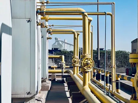
A leading 7 nm semiconductor fabrication plant located in Taiwan, a region facing severe water scarcity and mandated >70% water reuse by 2035, implemented a comprehensive wastewater treatment system to achieve 99.9% chromium removal and near-zero liquid discharge. The influent wastewater averaged 50 m³/h, with chromium concentrations ranging from 50–80 mg/L Cr⁶⁺, a pH between 3–5, and total suspended solids (TSS) at 200–400 mg/L. The implemented process design included: (1) equalization for flow and concentration stabilization, (2) chemical reduction using sodium metabisulfite at pH 2.5, confirmed by ORP monitoring, (3) precipitation with calcium hydroxide (Ca(OH)₂) at pH 8.5, (4) a lamella clarifier for solid-liquid separation, (5) a multimedia filter for TSS removal, (6) a 0.02 μm ultrafiltration (UF) system for chromium polishing, and (7) a reverse osmosis (RO) unit for maximizing water recovery to 90%. Sludge generated from precipitation was dewatered using an automated filter press for volume reduction. The system consistently achieved effluent chromium levels below 0.05 mg/L, meeting and exceeding all regulatory requirements. Water recovery reached 95%, significantly reducing freshwater intake. The total capital expenditure (CAPEX) for the system was $2.1 million, equating to $42,000 per m³/h of treatment capacity. Operating expenditure (OPEX) was remarkably low at $0.22/m³, broken down into chemicals ($0.12/m³), energy ($0.05/m³), and labor ($0.05/m³). With a freshwater cost of $0.70/m³, the system's ROI was calculated at 3.2 years. Key operational challenges encountered included ORP probe drift in the reduction stage, which was resolved through a strict weekly calibration protocol, and UF membrane fouling, managed by implementing a clean-in-place (CIP) cycle every 72 hours using 2% citric acid. This case study demonstrates the feasibility and economic viability of achieving ultra-high chromium removal and high water reuse rates in demanding semiconductor manufacturing environments. Advanced ZLD process design for semiconductor wastewater is no longer a futuristic concept but a present-day necessity.
Frequently Asked Questions
What is the optimal pH for chromium reduction in wafer fab wastewater?
The optimal pH for hexavalent chromium reduction is between 2 and 3, as specified by ASTM D1687-21. Operating below pH 2 significantly increases acid consumption and costs, while operating above pH 3 slows down the reduction kinetics, potentially leading to incomplete conversion of Cr⁶⁺ to Cr³⁺.
How much sodium metabisulfite is needed to reduce 1 mg of Cr⁶⁺?
The stoichiometric ratio requires approximately 3 mg of sodium metabisulfite (Na₂S₂O₅) per mg of Cr⁶⁺. However, practical dosing often includes a 20–50% excess (3–5 mg Na₂S₂O₅ per mg Cr⁶⁺) to account for potential oxidants in the wastewater and ensure complete reduction.
What are the disposal options for chromium sludge from wafer fab treatment?
Disposal options depend on the chromium concentration in the sludge. If the total chromium concentration exceeds 5 mg/kg, it is typically classified as hazardous waste and requires disposal in a licensed hazardous waste landfill. For non-hazardous sludge, stabilization/solidification techniques, such as cement encapsulation, can be employed before disposal. Disposal costs generally range from $200–$500 per ton, according to EPA 2024 hazardous waste guidelines.
Can ion exchange resins be regenerated for chromium removal?
Yes, ion exchange resins used for chromium removal can be regenerated. Strong base anion resins, commonly used for hexavalent chromium, are typically regenerated with a 4–6% sodium hydroxide (NaOH) solution. For trivalent chromium captured by cation resins, 10% sodium chloride (NaCl) or dilute acid can be used. Regeneration frequency varies but typically occurs every 50–100 bed volumes. The lifespan of ion exchange resins is generally 3–5 years.
What are the key differences between ultrafiltration and reverse osmosis for chromium polishing?
Ultrafiltration (UF) utilizes membranes with a pore size of approximately 0.02 μm and effectively removes suspended Cr³⁺ precipitates and larger colloidal particles. Reverse Osmosis (RO) membranes have much smaller pores and are designed to remove dissolved ions, achieving over 99% rejection of dissolved chromium species. UF is generally less energy-intensive and cheaper ($0.15–$0.30/m³ OPEX) but less effective for very low dissolved chromium concentrations. RO is more expensive ($0.30–$0.60/m³ OPEX) but is essential for achieving ultra-pure water and enabling ZLD by significantly concentrating the wastewater stream.
Related Equipment
The following HydropureWater products are engineered for the wastewater challenges discussed above:
- high-efficiency DAF system for chromium hydroxide sludge separation — view specifications, capacity range, and technical data
- automated filter press for chromium sludge dewatering to 30% solids — view specifications, capacity range, and technical data
- PVDF ultrafiltration membranes for chromium polishing in ZLD systems — view specifications, capacity range, and technical data
- PLC-controlled dosing for chromium reduction and precipitation chemicals — view specifications, capacity range, and technical data
Need a customized solution? Request a free quote with your specific flow rate and pollutant parameters.