Integrated circuit (IC) wastewater treatment requires specialized engineering to handle high volumes of ultrapure water (UPW) and hazardous contaminants like heavy metals, fluoride, and organic solvents. In 2025, semiconductor fabs generate wastewater containing up to 85% of chemical reagents used in fabrication (Nature, 2026), demanding treatment systems with 99%+ contaminant removal rates. This guide provides process flow diagrams, CAPEX/OPEX data, and a zero-liquid-discharge (ZLD) blueprint to help fabs meet global discharge standards while recovering 85-95% of water for reuse.
Why IC Wastewater Treatment is a Critical Challenge for Semiconductor Fabs
IC fabrication utilizes over 100 distinct chemical reagents, including hydrofluoric acid (HF), sulfuric acid (H₂SO₄), copper (Cu), nickel (Ni), and arsenic (As), with approximately 85% of these chemicals ultimately entering the wastewater stream (Nature, 2026). This complex effluent is characterized by high concentrations of total suspended solids (TSS), chemical oxygen demand (COD), heavy metals, and fluoride, posing significant environmental and regulatory challenges for IC manufacturing effluent treatment. The global semiconductor market, projected to reach $720 billion by 2025 with a 6.8% compound annual growth rate, intensifies wastewater volumes and increases regulatory scrutiny, requiring sophisticated semiconductor fab wastewater treatment solutions (Nature, 2026).
Meeting stringent regional discharge standards, such as those mandated by the US EPA and the EU Industrial Emissions Directive, is a constant operational hurdle. For instance, a 10 million gallon/day fab recently faced regulatory violations due to elevated TSS levels resulting from untreated photoresist waste, leading to substantial fines and operational disruption. Common compliance pitfalls extend beyond basic parameters to include emerging contaminants like per- and polyfluoroalkyl substances (PFAS) and trace heavy metals such as arsenic, which even at low concentrations, demand specialized removal strategies to avoid severe environmental penalties and reputational damage.
Contaminant Profile of IC Wastewater: What’s in Your Effluent?
IC wastewater streams are categorized into organic, inorganic, and suspended solids, each presenting unique treatment challenges. Organic contaminants primarily consist of photoresists, developers, and solvents (e.g., isopropyl alcohol, acetone), contributing significantly to COD. Inorganic pollutants include a wide array of heavy metals (e.g., copper, nickel, chromium, lead) originating from plating and etching processes, and high concentrations of fluoride from hydrofluoric acid etching. Suspended solids are typically composed of silica particles, colloidal matter, and residual polishing slurries (e.g., from Chemical Mechanical Planarization or CMP).
The concentration ranges of these contaminants vary significantly depending on the specific fab processes (e.g., etching, CMP, cleaning, plating). For example, copper concentrations can range from 5-50 mg/L, while hydrofluoric acid (measured as fluoride) can be present at 10-200 mg/L. Total suspended solids (TSS) often fall within 50-500 mg/L. Even low-concentration contaminants, such as arsenic at 0.1 mg/L, pose high environmental and health risks due to their toxicity. The US EPA and WHO toxicity thresholds highlight the critical need for precise removal of these trace elements, as they can bioaccumulate and cause long-term ecological damage.
Table 1: Typical Contaminant Profiles in IC Wastewater by Process Stream
| Contaminant Category | Key Contaminants | Typical Concentration Range (mg/L) | Primary Source Process | Environmental/Health Risk |
|---|---|---|---|---|
| Organic | COD (from photoresist, solvents) | 100-1000 | Photolithography, Cleaning | Oxygen depletion, aquatic toxicity |
| Inorganic (Heavy Metals) | Cu, Ni, Cr, Pb | 5-50 (Cu), 1-20 (Ni), 0.1-5 (Cr) | Plating, Etching | High toxicity, bioaccumulation, regulatory fines |
| Inorganic (Fluoride) | HF (as F-) | 10-200 | Wet Etching (e.g., silicon dioxide) | Aquatic toxicity, bone/dental issues |
| Inorganic (Trace) | As, Se | 0.01-0.5 | Ion Implantation, Etching | Extreme toxicity, carcinogen even at trace levels |
| Suspended Solids | TSS (silica, colloidal matter) | 50-500 | CMP, Cleaning, Grinding | Turbidity, membrane fouling, discharge violations |
Treatment Technologies for IC Wastewater: Process Selection Guide
Selecting the optimal semiconductor wastewater engineering specs requires a thorough understanding of various treatment technologies, balancing contaminant removal efficiency, operational costs, and scalability. Advanced Oxidation Processes (AOPs), such as Ozone/UV and Fenton’s reagent, are highly effective for organic contaminant removal, achieving COD reduction rates of 80-95%. However, AOPs typically incur high energy costs and can generate significant sludge, particularly with Fenton’s reagent due to iron hydroxide precipitation.
Membrane Systems, including Reverse Osmosis (RO), Nanofiltration (NF), and Membrane Bioreactors (MBR), offer superior rejection rates for a broad spectrum of pollutants. RO systems for heavy metal and fluoride removal achieve 95-99% rejection for heavy metals and 90-98% for fluoride, making them crucial for achieving stringent discharge limits and water reuse goals. NF is effective for divalent ions and larger organics, while MBRs are ideal for biological degradation of complex organic compounds combined with excellent solids separation. However, membrane systems are susceptible to fouling from silica, organics, and suspended solids, necessitating robust pretreatment. MBR integrated wastewater treatment systems are particularly useful for streams with high organic loads.
Electrochemical Methods, such as electrocoagulation and electro-oxidation, demonstrate high removal efficiencies for specific heavy metals, with electrocoagulation achieving up to 99% for copper and 95% for nickel. These methods often have lower sludge volumes compared to chemical precipitation and moderate energy consumption, typically ranging from 0.5-2 kWh/m³. Chemical Precipitation, involving pH adjustment and sulfide precipitation, remains a foundational step for heavy metal and fluoride removal. For example, adjusting pH to 9-10 precipitates metal hydroxides, while calcium chloride addition precipitates fluoride as CaF₂. Sludge volume reduction techniques, such as using filter presses for sludge volume reduction, are essential to manage the significant sludge generated by these processes.
Table 2: Comparison of IC Wastewater Treatment Technologies
| Technology | Key Contaminants Addressed | Typical Removal Efficiency | CAPEX (Relative) | OPEX (Relative) | Key Advantages | Key Limitations |
|---|---|---|---|---|---|---|
| Advanced Oxidation Processes (AOPs) | Organic (COD, TOC) | 80-95% (COD) | Medium-High | High (energy, chemicals) | Effective for recalcitrant organics | High energy consumption, potential sludge |
| Membrane Systems (RO/NF) | Heavy Metals, Fluoride, Salts, Organics | 95-99% (HM), 90-98% (F) | High | Medium (energy, pretreatment) | High water recovery, superior effluent quality | Fouling risk, high pressure, concentrate disposal |
| Membrane Bioreactor (MBR) | BOD, COD, TSS | >95% (BOD/TSS), 85-90% (COD) | High | Medium (energy, membrane cleaning) | High effluent quality, compact footprint | Membrane fouling, aeration costs |
| Electrochemical Methods | Heavy Metals, some Organics | 99% (Cu), 95% (Ni) | Medium | Medium (energy) | Lower sludge volume, no chemical addition (electrocoagulation) | Electrode passivation, energy intensity |
| Chemical Precipitation | Heavy Metals, Fluoride, TSS | >90% (HM), >95% (F) | Low-Medium | Medium (chemicals, sludge disposal) | Cost-effective, robust for high concentrations | High sludge generation, pH control critical |
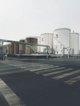
Zero-Liquid-Discharge (ZLD) for IC Fabs: Process Flow and Equipment Checklist
Achieving zero liquid discharge for semiconductor plants is a multi-stage process designed to maximize water recovery and minimize waste volume, typically achieving 85-95% water reuse for ultrapure water reuse in semiconductors. A typical ZLD blueprint for IC fabs involves three primary stages: pretreatment, concentration, and crystallization. For a 1 million gallon/day system, the CAPEX generally ranges from $5M-$20M, with OPEX between $0.50-$2.00/m³ depending on complexity and energy costs.
The pretreatment stage is critical for removing suspended solids, heavy metals, and other foulants that could compromise downstream membrane systems. This typically involves physical-chemical processes such as coagulation, flocculation, and clarification, often followed by DAF systems for IC wastewater pretreatment. Chemical precipitation for heavy metals and fluoride removal is also integrated here. After pretreatment, the water proceeds to the concentration stage, where membrane technologies like reverse osmosis (RO) and nanofiltration (NF) concentrate dissolved solids. RO systems typically achieve 75-85% water recovery in this stage, producing a clean permeate for reuse and a concentrated brine.
The final stage, crystallization, handles the highly concentrated brine from the membrane systems. This involves thermal processes such as evaporators (e.g., mechanical vapor recompression or multi-effect evaporators) and crystallizers, which further concentrate the brine to precipitate dissolved solids as a solid cake. These units achieve water recovery rates of 95-99% from the concentrated brine, leaving behind a minimal volume of solid waste for disposal. The overall process ensures that virtually no liquid effluent is discharged from the facility.
ZLD Process Flow Diagram (Text Description):
- Influent Wastewater: Raw IC wastewater enters the system.
- Pretreatment (DAF & Chemical Precipitation):
- Influent flows into a DAF system (e.g., Zhongsheng ZSQ series) to remove suspended solids, oils, and greases.
- Chemicals (coagulants, flocculants, pH adjusters) are added for heavy metal and fluoride precipitation.
- Clarification or secondary DAF separates precipitated solids.
- Membrane Concentration (RO/NF):
- Pretreated water passes through a robust filtration system (e.g., ultrafiltration or multimedia filters).
- Water then enters RO systems for heavy metal and fluoride removal (e.g., Zhongsheng JY series) to recover 75-85% as permeate.
- Permeate can be reused directly or further polished for UPW production.
- The concentrated brine (reject) proceeds to the next stage.
- Thermal Evaporation/Crystallization:
- RO reject is fed into evaporators (e.g., MVR or multi-effect) to further concentrate solids and recover water vapor.
- The highly concentrated slurry from the evaporator is sent to a crystallizer, where remaining dissolved solids precipitate into a solid cake.
- Condensate from evaporators is recovered and reused.
- Brine/Solid Disposal:
- The solid cake from the crystallizer is dewatered (e.g., using filter presses for sludge volume reduction) and sent for off-site disposal or beneficial reuse.
- Disinfection (e.g., with a ClO₂ generator, Zhongsheng ZS series) may be applied at various stages as needed.
Table 3: ZLD System Stages, Recovery Rates, and Equipment Checklist
| ZLD Stage | Primary Function | Typical Water Recovery from Stage (%) | Key Equipment (Example) | Zhongsheng Product Series |
|---|---|---|---|---|
| Pretreatment | Remove TSS, heavy metals, fluoride, organics | N/A (prepares water for next stage) | DAF system, Chemical Dosing, Clarifier, Multimedia Filter | ZSQ series (DAF) |
| Membrane Concentration | Remove dissolved solids, recover water | 75-85% (from feed to RO) | Reverse Osmosis (RO), Nanofiltration (NF) | JY series (RO) |
| Thermal Crystallization | Evaporate remaining water, crystallize solids | 95-99% (from concentrated brine) | Evaporator (MVR/MEE), Crystallizer, Heat Exchangers | N/A (Custom) |
| Sludge/Solid Management | Dewater solid waste for disposal | N/A (waste stream) | Filter Press (Plate and Frame), Sludge Thickener | Plate and Frame Filter Press |
Cost Breakdown and ROI for IC Wastewater Treatment Systems
Evaluating the financial viability of integrated circuit wastewater treatment solution systems requires a detailed analysis of both Capital Expenditure (CAPEX) and Operational Expenditure (OPEX), alongside a robust Return on Investment (ROI) calculation. Conventional treatment systems typically have a CAPEX range of $2.5M-$10M, while ZLD systems, due to their advanced technology and complexity, range from $5M-$40M for a medium to large-scale fab.
Breaking down CAPEX, major equipment components like RO systems can cost $500K-$2M, while DAF systems can range from $200K-$1M. Other significant CAPEX drivers include civil works, piping, instrumentation, and installation. OPEX for conventional systems generally falls between $0.30-$1.50/m³, whereas ZLD systems, with their higher energy and maintenance requirements, range from $0.50-$2.00/m³. These costs encompass energy consumption (pumping, heating), chemical reagents (coagulants, antiscalants, pH adjusters), labor for operation and maintenance, and waste disposal fees.
The ROI calculation for IC wastewater treatment systems, especially ZLD, hinges on several factors. Water reuse savings, typically valued at $0.50-$2.00/m³ depending on local water tariffs, represent a significant financial benefit. These savings are offset against discharge fees ($0.10-$0.50/m³) and potential regulatory penalties, which can range from $10K-$100K per violation event. A compelling case study involves a 5 million gallon/day fab that implemented a ZLD system achieving 85% water recovery. With an OPEX of $0.80/m³, this fab realized annual savings of approximately $1.2 million through reduced water intake, lower discharge volumes, and avoided penalties, demonstrating a strong ROI over a 3-5 year payback period.
Table 4: Cost Breakdown and ROI Factors for IC Wastewater Treatment Systems
| Cost Category | Conventional System Range | ZLD System Range | Key Drivers |
|---|---|---|---|
| CAPEX (Total) | $2.5M - $10M | $5M - $40M | Equipment, Civil Works, Installation, Permitting |
| - RO System | $500K - $1.5M | $1M - $2M | Capacity, membrane type, pretreatment |
| - DAF System | $200K - $500K | $300K - $1M | Flow rate, material of construction |
| - Evaporator/Crystallizer | N/A | $2M - $15M | Volume of concentrate, energy efficiency |
| OPEX (per m³) | $0.30 - $1.50 | $0.50 - $2.00 | Energy, Chemicals, Labor, Maintenance, Waste Disposal |
| - Energy Cost | $0.10 - $0.50 | $0.20 - $1.00 | Pumping, heating, aeration |
| - Chemical Cost | $0.05 - $0.30 | $0.10 - $0.40 | Coagulants, pH adjusters, antiscalants |
| - Waste Disposal | $0.05 - $0.20 | $0.02 - $0.15 (solids only) | Sludge volume, hazardous waste classification |
| ROI Factors | |||
| - Water Reuse Savings | N/A (unless partial recovery) | $0.50 - $2.00 / m³ recovered | Local water cost, volume recovered |
| - Avoided Discharge Fees | $0.10 - $0.50 / m³ discharged | Up to 100% avoided | Local discharge regulations |
| - Avoided Penalties | $10K - $100K / event | Minimization of risk | Severity of violation, regulatory body |
Frequently Asked Questions
Q: What are the discharge limits for IC wastewater in the EU and US?
A: In the EU, the Industrial Emissions Directive typically sets limits such as TSS < 30 mg/L, COD < 125 mg/L, and heavy metals like copper (Cu < 0.5 mg/L) and nickel (Ni < 0.5 mg/L). US EPA limits vary significantly by state and local jurisdiction; for example, California may impose stricter limits such as Cu < 0.4 mg/L and Ni < 0.2 mg/L for certain discharges.
Q: How much does a ZLD system cost for a 1M gallon/day IC fab?
A: For a 1 million gallon/day (approximately 3,785 m³/day) IC fab, the Capital Expenditure (CAPEX) for a ZLD system typically ranges from $5M-$10M. The Operational Expenditure (OPEX) can be between $0.50-$1.50/m³. The exact ROI depends heavily on local water tariffs, discharge fees, and the value of recovered water for reuse.
Q: Can IC wastewater be reused for UPW production?
A: Yes, treated IC wastewater can be reused for ultrapure water (UPW) production, but it requires highly advanced post-treatment. This typically involves a combination of reverse osmosis (RO) followed by electrodeionization (EDI) or mixed-bed ion exchange (MBIX) to achieve the stringent purity levels required for semiconductor manufacturing. Recovery rates for UPW quality can range from 70-90% of the initial treated effluent.
Q: What are the most common treatment failures in IC wastewater systems?
A: Common treatment failures include membrane fouling, often caused by inadequate pretreatment leading to silica or organic accumulation on membrane surfaces. Another frequent issue is inadequate pH control, which can lead to inefficient heavy metal precipitation or re-dissolution of metals. Insufficient sludge dewatering is also a significant problem, increasing the volume and cost of waste disposal.