Home>Blog>Industry News>Semiconductor Wastewater Zero Liquid Discharge: Engineering Specs, Cost Data & Hybrid System Design 2026
Semiconductor Wastewater Zero Liquid Discharge: Engineering Specs, Cost Data & Hybrid System Design 2026
Industry News
Zhongsheng Engineering Team
Semiconductor Wastewater Zero Liquid Discharge: Engineering Specs, Cost Data & Hybrid System Design 2025
Semiconductor fabs generate 200-1,000 m³/day of acidic wastewater, typically containing 50-500 ppm hydrofluoric acid (HF) and up to 1M sulfuric acid (H₂SO₄). Meeting increasingly stringent environmental regulations necessitates zero liquid discharge (ZLD) systems for these complex streams. Hybrid forward osmosis-nanofiltration (FO-NF) systems achieve >90% copper ion rejection and 95%+ water recovery, offering an energy-efficient path. In contrast, thermal evaporator-crystallizer systems effectively handle high-TDS brines but incur 3-5x higher energy costs. This comprehensive engineering guide provides 2025 technical specifications, detailed cost data, and a robust decision framework for selecting the optimal ZLD technology tailored to specific wastewater compositions and fab operational constraints.
Why Semiconductor Fabs Need Zero Liquid Discharge: Regulatory Pressures and Water Scarcity
EPA and EU Industrial Emissions Directive 2010/75/EU mandate strict discharge limits for semiconductor wastewater, with fluoride often capped at 4-10 ppm in key manufacturing hubs. For instance, in Taiwan, permit limits for fluoride can be as low as 5 ppm, while in Arizona, EPA regulations drive similar stringent requirements. Non-compliance carries substantial financial penalties; Intel faced a $14 million fine in 2022 for fluoride violations in a US facility, according to EPA enforcement data. Beyond regulatory compliance, severe water scarcity in major semiconductor production regions significantly impacts operational continuity. Taiwan experienced a 2021 drought that reduced fab output by an estimated 15%, highlighting the vulnerability of water-intensive industries. Similarly, Arizona faces ongoing groundwater depletion challenges, and Singapore relies heavily on advanced water recycling mandates (NEWater) to secure its supply. These pressures compel fabs to adopt zero liquid discharge (ZLD) strategies not just for environmental stewardship, but for critical operational resilience. TSMC, for example, invested $100 million in ZLD infrastructure for its Arizona fab, explicitly to secure a 20-year water supply and mitigate future risks, as detailed in their 2023 sustainability report.
Region/Authority
Key Contaminant
Typical Discharge Limit (ppm)
Impact on Fabs
EPA (USA, e.g., Arizona)
Fluoride (F⁻)
4-10
Risk of significant fines, operational shutdowns
EU Industrial Emissions Directive
Fluoride (F⁻)
5-10
Strict permitting, Best Available Techniques (BAT) compliance
Taiwan EPA
Fluoride (F⁻)
5
High water scarcity, mandates for water reuse/ZLD
Singapore (PUB)
TDS, Metals
Stringent (ZLD encouraged)
NEWater mandates, high water costs, operational resilience
Global (Industry Best Practice)
Copper (Cu²⁺)
<0.1
Metal recovery potential, environmental impact
Semiconductor Wastewater Composition: Key Contaminants and Treatment Challenges
semiconductor wastewater zero liquid discharge - Semiconductor Wastewater Composition: Key Contaminants and Treatment Challenges
Semiconductor manufacturing processes generate diverse and complex wastewater streams, fundamentally characterized by specific contaminants like hydrofluoric acid (HF), sulfuric acid (H₂SO₄), and heavy metals, each presenting unique treatment challenges for zero liquid discharge (ZLD) systems. Typical fab wastewater includes HF at concentrations ranging from 200-500 ppm F⁻, sulfuric acid at 0.1-1.0M, and copper (Cu²⁺) at 50-200 ppm, often originating from etching and plating processes. Additionally, total organic carbon (TOC) from photoresists and developers can range from 100-1,000 ppm, while emerging concerns include per- and polyfluoroalkyl substances (PFAS) from chemical mechanical planarization (CMP) slurries. The pH of these streams varies significantly, typically 2-5 for acidic effluents and 8-10 for alkaline waste, complicating direct treatment without extensive pH adjustment.
The presence of copper (Cu²⁺) is particularly notable, not just as a pollutant, but as a potential resource. Forward osmosis (FO) processes have demonstrated the ability to concentrate Cu²⁺ by more than three-fold in the feed stream, highlighting opportunities for valuable metal recovery, as reported in recent academic studies (PubMed, 2025). Effective pretreatment for these varied streams is critical before ZLD, often involving coagulation-flocculation, precipitation, or advanced oxidation processes. For example,
electrocoagulation for metal removal in semiconductor wastewater can be a vital first step, while MBR systems for organic removal before ZLD address TOC challenges.
Fab Process
Typical Contaminants
Concentration Range
Regulatory Limit (Example F⁻)
Treatment Challenge
Etching
HF, HNO₃, F⁻, NH₄⁺
200-500 ppm F⁻
4-10 ppm
Fluoride precipitation, complexation
Cleaning/Drying
H₂SO₄, H₂O₂, IPA, Metals
0.1-1.0 M H₂SO₄, 50-200 ppm Cu²⁺
<0.1 ppm Cu²⁺
Acid neutralization, metal recovery
Lithography
Photoresists, Developers, Solvents
100-1,000 ppm TOC
Low BOD/COD
Organic removal, biodegradability
CMP
Slurries, Metals, PFAS
High TDS, 10-100 ppb PFAS
Emerging limits for PFAS
Particulate removal, PFAS destruction
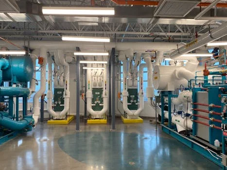
Hybrid FO-NF Systems: Engineering Mechanics and Performance Data
Hybrid forward osmosis-nanofiltration (FO-NF) systems offer an advanced membrane-based approach to zero liquid discharge (ZLD) for semiconductor wastewater, leveraging osmotic pressure for efficient water recovery and contaminant rejection. The initial forward osmosis (FO) process utilizes HF wastewater (typically pH 3-5) as the feed stream, while a neutralized Na₂SO₄ solution (e.g., 1.0 M) serves as the draw solution. This configuration allows water to passively diffuse from the lower osmotic pressure HF stream to the higher osmotic pressure Na₂SO₄ stream, driven by the osmotic gradient. Studies have demonstrated that this FO process can achieve greater than 55% dilution of the Na₂SO₄ waste stream while simultaneously providing over 50% rejection of all ionic contaminants in the HF wastewater, with a particularly high rejection rate of over 90% for copper ions (PubMed, 2025). This high copper rejection also leads to a more than three-fold concentration of Cu²⁺ in the feed stream, facilitating potential metal recovery.
Following the FO stage, the diluted Na₂SO₄ draw solution, now enriched with water, is directed to a two-stage nanofiltration (NF) process. NF membranes are selectively permeable, allowing water molecules and monovalent ions to pass while rejecting divalent ions like sulfate and larger organic molecules. This multi-stage NF process is engineered to maximize water recovery from the diluted draw solution, producing high-quality permeate suitable for reuse as ultrapure water (UPW) makeup in the fab (ScienceDirect, 2025). Energy consumption for membrane systems, including NF, typically ranges from 5-15 kWh/m³, significantly lower than thermal methods. A typical process diagram involves the HF wastewater entering the FO membrane module, with the concentrated HF stream potentially going to metal recovery or further treatment, and the diluted draw solution proceeding to a series of NF stages for water recovery and brine concentration. The final concentrated brine from the NF stages may then be sent to a small crystallizer or further processed by semiconductor-grade RO systems for ZLD pretreatment for even higher recovery.
Limitations of FO-NF systems include membrane fouling from high concentrations of organics or particulates in the feed, and potential scaling from high-TDS streams if not adequately pretreated. Mitigation strategies involve robust upstream filtration, precision chemical dosing for pH adjustment and metal precipitation using an automatic chemical dosing system, and regular membrane cleaning-in-place (CIP) protocols.
Parameter
Forward Osmosis (FO) Stage
Nanofiltration (NF) Stage
Feed Stream
HF Wastewater (pH 3-5)
Diluted Na₂SO₄ Draw Solution
Draw Solution
1.0 M Neutralized Na₂SO₄
N/A (Permeate & Concentrate)
Water Flux (Typical)
5-15 LMH (L/m²/hr)
15-30 LMH
Cu²⁺ Rejection
>90% (in FO feed)
>95% (divalent ions)
Ionic Contaminant Rejection
>50% (total ionic)
>90% (divalent), 30-70% (monovalent)
Water Recovery Rate
55%+ (of draw solution volume)
95%+ (of NF feed)
Energy Consumption (Overall)
Low (primarily pumping)
5-15 kWh/m³ (for NF stages)
Membrane Types
Thin-film composite (TFC) FO
Thin-film composite (TFC) NF
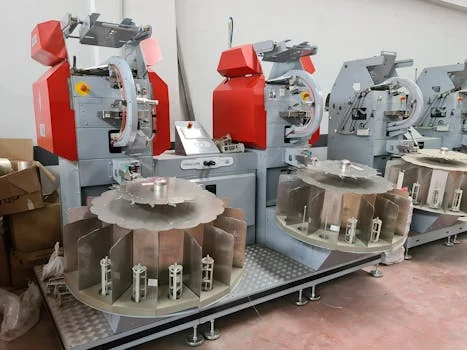
Thermal ZLD Systems: Evaporators, Crystallizers, and Energy Trade-offs
semiconductor wastewater zero liquid discharge - Thermal ZLD Systems: Evaporators, Crystallizers, and Energy Trade-offs
Thermal zero liquid discharge (ZLD) systems, primarily comprising evaporators and crystallizers, utilize heat to separate water from dissolved solids, providing a robust solution for high-salinity and complex industrial wastewater streams prevalent in semiconductor manufacturing. These systems are particularly effective for brines that membrane technologies cannot efficiently treat due to high osmotic pressure or fouling potential. Veolia's approach to thermal ZLD, for instance, typically involves brine concentrators that achieve 90-95% water recovery, followed by crystallizers that reduce the remaining brine to a solid, disposable waste or a valuable byproduct (Veolia Water Technologies, 2024). This method ensures minimal liquid discharge and maximizes water recovery.
A significant trade-off with thermal ZLD is energy consumption. These systems typically require 50-100 kWh/m³ of treated water, a substantially higher demand compared to the 5-15 kWh/m³ for membrane-based systems. Technologies like mechanical vapor recompression (MVR) evaporators can reduce energy use by recovering latent heat, but the overall energy footprint remains considerable. Saltworks Technologies offers modular systems that integrate advanced pretreatment, such as XtremeUF for ultrafiltration, with their SaltMaker MVR evaporator and crystallizer units to handle challenging fab wastewater streams including hydrofluoric acid, PFAS, and high-TDS brines (Saltworks Technologies, PDF).
Byproduct recovery is a key consideration. From H₂SO₄ neutralization, gypsum (calcium sulfate) can be recovered, potentially for industrial use if purity is sufficient. Similarly, copper hydroxide can be precipitated from HF streams, offering a potential revenue stream if contaminants are removed to meet market specifications. For instance, chlorine dioxide for TOC reduction in semiconductor wastewater may be integrated upstream to ensure byproduct purity. The solid waste generated by crystallizers, such as mixed salts, requires careful handling and disposal, often dewatered using a plate and frame filter press for sludge dewatering before landfilling or further processing. Thermal systems also demand a larger physical footprint, typically requiring 2-3 times more space than equivalent capacity membrane systems due to the size of evaporators, heat exchangers, and associated auxiliary equipment. This can be a critical constraint for space-limited fabs.
ZLD Technology Comparison: Membrane vs Thermal Systems for Semiconductor Fabs
Selecting the optimal zero liquid discharge (ZLD) technology for a semiconductor fab necessitates a direct, data-driven comparison between membrane-based and thermal systems, as each offers distinct advantages and limitations depending on specific wastewater characteristics and operational priorities. Membrane-based systems, particularly FO-NF hybrids, excel in energy efficiency and smaller footprints, making them ideal for treating lower-TDS streams and facilities with space constraints. Thermal systems, on the other hand, provide robustness for extremely high-TDS brines and challenging wastewater compositions where membrane performance degrades.
For example, TSMC has implemented membrane-based ZLD solutions in its Taiwan fabs, prioritizing water recycling and energy efficiency in a region with high electricity costs and land scarcity. Conversely, Intel has utilized thermal ZLD systems in some of its Arizona facilities, where the ability to handle highly concentrated brines and achieve complete solid waste discharge might be prioritized over the highest energy efficiency, given different local utility costs and disposal options. Emerging technologies, such as FO-RO hybrids and electrodialysis reversal (EDR) for selective ion removal, continue to advance, offering even greater customization and efficiency for specific semiconductor wastewater challenges.
Parameter
FO-NF Hybrid ZLD System
Thermal ZLD System
CAPEX (200-1000 m³/day)
$2M - $6M
$5M - $10M
OPEX (Energy)
5-15 kWh/m³
50-100 kWh/m³
Water Recovery Rate
90-98%
95-99%
Footprint (Relative)
Compact (1x)
Large (2-3x)
Maintenance
Membrane cleaning/replacement
Scaling, corrosion, mechanical
Scalability
Modular, relatively easy
More complex, larger increments
Byproduct Recovery
Concentrated metals, acids (liquid)
Solid salts, metal hydroxides (solid)
Regulatory Compliance
High (meets discharge limits)
Excellent (zero liquid discharge)
Suitability for HF/H₂SO₄
Good (with pretreatment for HF)
Excellent (robust for high TDS)
Typical Application
Lower-TDS streams, water reuse, space-constrained fabs
2025 Cost Analysis: CAPEX, OPEX, and ROI for Semiconductor ZLD Systems
semiconductor wastewater zero liquid discharge - 2025 Cost Analysis: CAPEX, OPEX, and ROI for Semiconductor ZLD Systems
A comprehensive 2025 cost analysis for semiconductor zero liquid discharge (ZLD) systems reveals that initial capital expenditure (CAPEX) typically ranges from $2 million to $10 million for systems treating 200-1,000 m³/day, with operational expenditure (OPEX) heavily influenced by energy consumption and membrane replacement cycles. Membrane-based systems, such as FO-NF hybrids, generally fall on the lower end of the CAPEX spectrum ($2M-$6M), while robust thermal evaporator-crystallizer systems are at the higher end ($5M-$10M) due to more complex metallurgy and larger equipment.
OPEX components are critical for long-term financial viability. Energy consumption typically accounts for 50-70% of total OPEX for thermal systems, whereas it is a smaller, though still significant, portion for membrane systems. Membrane replacement costs, occurring every 3-5 years, represent 10-20% of OPEX for membrane technologies. Other OPEX factors include labor (5-10%), chemicals for pretreatment and cleaning (5-15%), and waste disposal.
The return on investment (ROI) for ZLD systems is primarily driven by water savings and regulatory avoidance. With recycled water valued at $0.50-$2.00/m³ (depending on local water costs and purity requirements), ZLD systems can achieve a 3-7 year payback period. This ROI calculation must also factor in the avoided costs of non-compliance, such as fines and production losses, which can be substantial. Hidden costs include the disposal of concentrated brine or solid waste, which can range from $0.10-$0.50/kg, and the costs associated with membrane fouling mitigation or ensuring system redundancy for critical fab operations. An interactive calculator, typically provided by ZLD solution providers, can help fabs model their specific ROI based on local water costs, wastewater volume, and contaminant profile.
Cost Category
Sub-component
Membrane ZLD (FO-NF Hybrid)
Thermal ZLD (Evaporator-Crystallizer)
CAPEX (Estimated for 500 m³/day)
Equipment Purchase
$1.5M - $3.5M
$3.5M - $7.0M
Installation & Commissioning
$0.5M - $1.5M
$1.0M - $2.5M
Engineering & Design
$0.2M - $0.5M
$0.3M - $0.8M
Total CAPEX Range
$2.2M - $5.5M
$4.8M - $10.3M
OPEX (Estimated per m³ treated)
Energy Consumption
$0.05 - $0.20/m³
$0.50 - $2.00/m³
Membrane/Spares Replacement
$0.08 - $0.15/m³
$0.02 - $0.05/m³ (for pumps/valves)
Chemicals (Pretreatment, Cleaning)
$0.05 - $0.10/m³
$0.05 - $0.15/m³
Labor & Maintenance
$0.05 - $0.10/m³
$0.08 - $0.18/m³
Total OPEX Range (per m³)
$0.23 - $0.55/m³
$0.65 - $2.38/m³
Financial Benefits
Water Savings (Recycled Water Value)
$0.50 - $2.00/m³ (site-specific)
Regulatory Avoidance (Fines, Production Loss)
Significant, highly variable (e.g., $14M fine avoidance)
Frequently Asked Questions
Addressing common inquiries about zero liquid discharge (ZLD) systems in semiconductor manufacturing clarifies key technical, operational, and financial considerations for fab engineers and environmental managers.
What is the primary benefit of ZLD for semiconductor fabs?
The primary benefit of ZLD for semiconductor fabs is securing operational resilience through water independence and ensuring stringent environmental compliance. By recycling 90-99% of wastewater, fabs mitigate risks from water scarcity, reduce discharge liabilities, and avoid costly regulatory fines, ultimately contributing to sustainable growth and a reduced environmental footprint.
How do FO-NF systems handle HF wastewater?
FO-NF systems treat HF wastewater by using it as a feed stream in the forward osmosis (FO) stage. The osmotic pressure drives water out of the HF stream, concentrating contaminants like fluoride and copper, while a draw solution (e.g., Na₂SO₄) is diluted. The diluted draw solution then undergoes nanofiltration (NF) to recover high-purity water, effectively separating water from dissolved salts and enabling potential byproduct recovery.
What are the main energy drivers for thermal ZLD?
The main energy drivers for thermal ZLD systems are the latent heat of vaporization required to evaporate water and the energy needed for mechanical vapor recompression (MVR) or steam generation. These processes are energy-intensive, consuming 50-100 kWh/m³ of treated water, compared to 5-15 kWh/m³ for membrane systems. Optimizing heat recovery is crucial for minimizing their operational costs.
Can valuable metals be recovered from ZLD processes?
Yes, valuable metals such as copper (Cu²⁺) can be recovered from semiconductor ZLD processes. Membrane systems like FO can concentrate copper by over three-fold in the feed stream, facilitating subsequent precipitation or electrochemical recovery. Thermal systems can also concentrate metals into solid byproducts, which, if sufficiently pure, can be processed for resale, turning a waste stream into a potential revenue source.
What are the typical payback periods for ZLD investments?
Typical payback periods for ZLD investments in semiconductor fabs range from 3 to 7 years. This ROI is primarily driven by significant water savings (reducing costs for fresh water intake and wastewater discharge) and the avoidance of substantial regulatory fines and potential production losses due to water scarcity or non-compliance. The exact payback period depends on local water costs, system size, and wastewater characteristics.
Zhongsheng Engineering Team
Our team of wastewater treatment engineers has over 15 years of experience designing and manufacturing DAF systems, MBR bioreactors, and packaged treatment plants for clients in 30+ countries worldwide.