Why an Electrodialysis Maintenance Program Matters in 2026
Electrodialysis (ED) uses an electric field to drive dissolved ions through stacked anion-exchange and cation-exchange membranes, producing a dilute (product) stream and a concentrate (brine) stream. The process recovers up to 90% of feedwater as usable product, versus the 50–75% typical of reverse osmosis (S5). That recovery advantage erodes quickly when the stack fouls: a single missed CIP cycle can drop stack efficiency by 10–20% within weeks and force a full membrane replacement inside two years instead of seven.
Operators encounter two recurring failure modes—organic and inorganic fouling on the ion-exchange membranes, and electrode scaling on the anode and cathode end-plates. Both respond predictably to scheduled cleaning if the chemistry is right, and both destroy membranes if it is wrong. This guide structures the work into four tiers—daily walk-around, weekly and monthly preventive tasks, quarterly Clean-In-Place (CIP), and annual overhaul—so a shift operator can execute the program independently.
Daily Operating Checks: 10-Minute Operator Walk-Around
Voltage creep at constant current is the primary predictor of unplanned ED downtime, signaling membrane-surface blockage. Catching that drift in the first 10 minutes of a shift is the goal of the daily check.
Log five parameters every two hours (or pull them continuously from a SCADA system for continuous ED monitoring): stack voltage (V), current density (mA/cm²), dilute-stream conductivity (µS/cm), concentrate-stream conductivity (µS/cm), and inter-stream pressure drop (bar). Compare each reading to the rolling 30-day baseline. A voltage rise of more than 10% at constant current is the universal early-warning threshold for organic or biological fouling on the anion-exchange membrane (AEM). A creeping pressure drop without a flow change points to spacer plugging. A dilute-stream conductivity drift upward at constant voltage points to membrane selectivity loss or scale formation.
| Parameter | Log cadence | Early-warning signal | Likely fault |
|---|---|---|---|
| Stack voltage (V) | Every 2 h | Rise >10% at constant I | AEM fouling or scaling |
| Current density (mA/cm²) | Every 2 h | Cannot hold setpoint | Rectifier or electrode issue |
| Dilute conductivity (µS/cm) | Every 2 h | Drift up at constant V | Membrane selectivity loss |
| Concentrate conductivity (µS/cm) | Every 2 h | Flat or falling | Recirculation pump or flow fault |
| Pressure drop (bar) | Every 2 h | Rise without flow change | Spacer fouling or biofilm |
| Electrode rinse flow | Each shift | Below minimum | Gas-pocket buildup, scale on electrode |
Finish the walk-around with a visual check of the stack frame for weep marks or salt creep at tie-rod penetrations, and confirm the electrode rinse-water flow is at manufacturer-specified minimum. Electrode rinse flow is the primary defense against anode scaling and cathode gas-pocket formation; if the rinse stream stagnates, the electrode degrades within weeks.
Weekly and Monthly Preventive Tasks
Weekly and monthly tasks target slow-drift failures—electrode wear, gasket compression set, and pump degradation—that daily logs cannot detect and quarterly CIP cannot reverse.
Weekly, torque-check the stack frame tie-rods to manufacturer specification (typically 8–12 N·m, datasheet-dependent). Inspect electrode cable connections for green or white corrosion byproducts; loose or corroded connections cause voltage loss and ground-fault trips. Sample the feed stream for Silt Density Index (target SDI <5 for ED) and free chlorine (target <0.1 ppm—chlorine above this attacks the anion-exchange membrane polymer backbone and shortens life from years to months). Where feed pH drifts outside the membrane window, an automatic chemical dosing system for CIP and pH control maintains the setpoint without operator intervention.
Monthly, calibrate conductivity meters against a known standard and verify pressure-transmitter zero. Inspect rectifier output: ripple above 5% of setpoint voltage accelerates membrane degradation through localized heating. Drain and flush both electrode compartments with deionized water to clear gas-pocket buildup—hydrogen at the cathode, oxygen and chlorine at the anode. Review trend logs for the voltage-creep signature described in the daily-check section; this is the leading indicator of membrane surface blockage and the trigger to schedule CIP ahead of the quarterly cycle.
Quarterly Clean-In-Place (CIP): Chemistry, Sequence and Contact Times
Quarterly CIP is the highest-ROI maintenance activity in any ED program. The two-step sequence—alkaline wash to remove organic and biological fouling, acid wash to remove inorganic scale—restores membrane performance to within 5–10% of factory baseline and resets the voltage-creep clock.
- Alkaline wash first. Circulate 0.5–1% NaOH at 30–40°C for 60–90 minutes. This dissolves humic substances, surfactants, and biological biofilm that accumulate on the AEM surface. Confirm temperature and concentration against the specific membrane datasheet; exceeding these limits attacks the membrane polymer.
- Flush with RO or deionized water until discharge pH returns to within 1 unit of feed pH. Cross-reaction between residual caustic and incoming acid forms salt precipitates that defeat the purpose of the acid step.
- Acid wash second. Circulate 0.5–2% HCl (or 2–3% citric acid as a milder alternative on chlorine-sensitive membranes) at 30–40°C for 60–90 minutes. This dissolves calcium carbonate, calcium sulfate, and metal hydroxides—the dominant scale species in RO concentrate and brackish feed duty.
- Final flush with RO or deionized water to discharge pH 5–9, then return the stack to service.
| Step | Chemical | Concentration | Temperature | Contact time | Target foulant |
|---|---|---|---|---|---|
| 1. Alkaline wash | NaOH | 0.5–1% | 30–40°C | 60–90 min | Organic, biological |
| 2. Flush | RO / DI water | — | Ambient | Until pH neutral | Caustic residue |
| 3. Acid wash | HCl or citric acid | 0.5–2% HCl, 2–3% citric | 30–40°C | 60–90 min | Scale (CaCO₃, metals) |
| 4. Final flush | RO / DI water | — | Ambient | To pH 5–9 | Acid residue |
Validate every CIP by measuring stack resistance at constant current before and after the cycle. A resistance reduction greater than 15% at the same current setpoint confirms successful cleaning. If resistance has not dropped, the foulant may be biological (add a chlorine-compatible biocide to the alkaline step, then flush thoroughly) or the membrane may be at end of life. The order matters: alkaline-then-acid is the standard sequence because residual organic film blocks acid access to scale, and reversing the order leaves scale under a re-deposited organic layer.
Annual Overhaul: Membrane, Spacer and Electrode Replacement
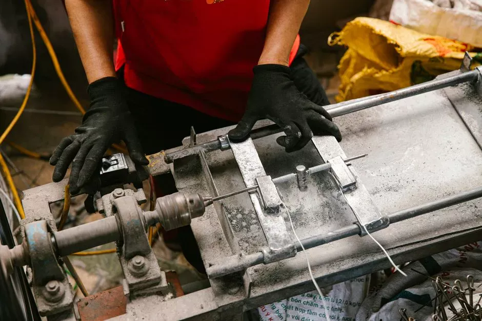
Every ED stack contains three consumable lifelines—membranes, spacers/gaskets, and electrode coatings. Annual overhaul provides the opportunity to inspect, measure, and reorder parts before failure forces a shutdown.
Ion-exchange membrane service life is typically 5–8 years in clean feedwater duty (brackish, RO concentrate with moderate hardness) and 2–4 years in textile dye liquor or heavy-metal-bearing effluent. The dominant wear mechanisms are irreversible fouling, chemical attack, and mechanical damage during maintenance. Always confirm the manufacturer's rated life for the specific feed chemistry.
Spacers and gaskets are mechanical items: inspect annually, replace every 2–3 years, or sooner if pressure drop rises more than 20% after a confirmed successful CIP. Keeping spare ion-exchange and RO/UF membrane elements and gaskets in stock avoids a 6–10 week lead-time shutdown when a replacement becomes urgent.
Electrode inspection: titanium-coated anodes typically outlast graphite but require annual acid cleaning to remove metal-oxide deposits. Cathodes may need recoating in high-chloride feed, where chloride accelerates corrosion. Inspect rectifier ripple and confirm the ground-fault interrupter trips on test; an undetected ground fault will destroy the next membrane change-out.
Troubleshooting Matrix: Symptom to Cause to Fix
A structured troubleshooting matrix allows the on-call engineer to map symptoms to root causes and corrective actions in under 30 minutes. The five ED faults below account for the majority of unscheduled service calls. Where biological fouling is suspected, deploying ultrafiltration pretreatment upstream of the ED stack is the most effective long-term fix.
| Symptom | Probable cause | Fix |
|---|---|---|
| Voltage rises at constant current | Organic or biological fouling on AEM | Alkaline CIP + biocide if biological; review feed pretreatment |
| Dilute conductivity drifts up at constant V | Membrane selectivity loss or scale | Acid CIP; check feed hardness; verify pH window |
| Inter-stream pressure drop rises without flow change | Spacer fouling or biofilm | Alkaline CIP with surfactant; inspect spacers at next outage |
| Visible leakage at stack frame | Gasket compression set or tie-rod torque loss | Re-torque to spec; replace compressed gaskets |
| Rectifier trips or ground fault | Electrode coating failure or water ingress | Isolate stack, megger-test electrodes, replace coated assembly |
Two principles cut diagnosis time in half. First, every electrical symptom (rectifier trip, ground fault, inability to hold current) starts at the electrodes, not the membranes—megger-test first. Second, every hydraulic or quality symptom (pressure drop, conductivity drift, voltage creep) starts at the membrane or spacer—CIP first, inspection second.
Feedwater Pretreatment: The First Line of Defence

Approximately 70% of ED fouling is preventable upstream. The feedwater specification that protects the stack is typically: turbidity <1 NTU, SDI <5, free chlorine <0.1 ppm, iron and manganese each <0.05 ppm, and hardness moderated to <200 ppm as CaCO₃ for most anion-exchange membranes. Confirm exact values against the membrane datasheet.
The pretreatment train that delivers this quality is: multi-media filter → cartridge filter (5–10 µm) → optional ultrafiltration → activated carbon (dechlorination) → ED. A multi-media filter for ED feedwater polishing handles the bulk of turbidity and iron, and ultrafiltration pretreatment upstream of the ED stack removes colloids and biological precursors that would otherwise drive monthly CIP. The pump cavitation troubleshooting guide covers the recirculation-pump side of the same pretreatment train.
Frequently Asked Questions
How often should an electrodialysis stack be CIP-cleaned?
Quarterly CIP is the baseline, but operators should run an early alkaline wash as soon as voltage creep exceeds 10% at constant current. Holding the quarterly schedule keeps resistance within 5–10% of factory baseline; missing it shortens membrane life by 30–50% (HydropureWater field data, 2026).
What is the typical CIP chemical concentration for ED membranes?
The standard sequence is 0.5–1% NaOH at 30–40°C for 60–90 minutes, followed by 0.5–2% HCl or 2–3% citric acid at 30–40°C for 60–90 minutes, with RO or deionized flushes between stages. Always confirm concentrations and temperature limits against the specific membrane datasheet before each CIP.
How long do ion-exchange membranes last in industrial ED service?
Industry-typical service life is 5–8 years in clean feedwater duty (brackish, RO concentrate) and