

Why Portland Semiconductor Fabs Need a Different Clarification Logic in 2026
Portland semiconductor fabs generating CMP slurry, fluoride, and trace-metal waste should select a DAF system over a conventional gravity lamella clarifier in 2026, because DAF microbubble flotation (30–50 micron bubbles) reliably captures low-density abrasive particles and colloidal silica that settle poorly, and pairs cleanly with coagulation/flocculation required by 40 CFR Part 468 categorical pretreatment standards enforced through Oregon DEQ and the City of Portland BES industrial pretreatment program. Semiconductor effluent differs significantly from food-processing or refinery wastewater, and most published clarifier comparison material assumes the wrong chemistry.
Wafer-fab primary clarification in 2026 is driven by four sub-streams that behave nothing like fats, oils, and grease (FOG): chemical mechanical planarization (CMP) slurry with colloidal silica or ceria at 100–500 mg/L TSS, back-grind fines from wafer thinning, fluoride-bearing scrubber blowdown from HF and NF₃ processes, and tetramethylammonium hydroxide (TMAH) developer waste. Each carries trace metals (Cu, Ni, W, Co) that fall under 40 CFR Part 468 categorical standards, and each fails to settle well because the dominant particles are either sub-10 µm or stabilized by chemistry.
Portland's regulatory envelope compounds the problem. Oregon DEQ implements the NPDES program, but industrial users discharging to the City of Portland's Columbia Boulevard wastewater treatment plant must also satisfy the BES industrial pretreatment program limits, which set pH 5–11 and TSS <50 mg/L on a monthly average basis for most categorical discharges. The combined federal-state-municipal permit path means a single clarifier choice has to hit TSS, fluoride, and trace-metal triggers simultaneously. Sorting mixed-oxide and CMP wastewater against that compliance wall is where lamella-only designs start to look under-engineered, and where a DAF-first approach earns its place.
How DAF and Lamella Clarifiers Actually Separate Solids
DAF and lamella clarifiers are both physical separation devices, but the physics they exploit are not interchangeable. A DAF saturates a pressurized side-stream (typically 4–6 bar) with air, then releases it through needle valves or nozzles into the main flotation tank; the resulting pressure drop nucleates 30–50 µm microbubbles that attach to conditioned floc and lift it to the surface, where a paddle skimmer removes the floated layer. Heavier silica and metallic particles that do not attach report to the underflow auger at the bottom of the tank (per SigmaDAF product documentation, 2026-04).
A lamella clarifier is a gravity settler with inclined plates (typically 55–60° from horizontal) stacked at close spacing to multiply the effective settling area. It relies on Stokes' law: particles with sufficient settling velocity contact the plate underside and slide down into a hopper. Surface loading rates on lamella packs run 20–40 m/h, which is high compared with conventional clarifiers but still constrained by particle density and size.
Two operational consequences follow. First, DAF does not strictly require coagulation/flocculation, but it performs poorly without it; chemical conditioning is what grows microfloc large enough to be lifted by a 30–50 µm bubble. Second, lamella clarifiers do not strictly require chemical dosing either, but the same microfloc growth step dramatically improves their removal of colloidal silica because that material has a near-neutral settling velocity. Without conditioning, a lamella pack struggles on streams that DAF handles as a baseline. For a Portland fab whose sub-streams include 50–200 mg/L colloidal silica from CMP, that asymmetry is the entire decision.
Head-to-Head: DAF vs Lamella Clarifier for Semiconductor Effluent
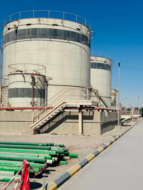
The procurement question usually lands as "which unit gives us the lowest TSS to the sewer?" DAF is superior for colloidal and low-density streams, lamella is better for high-density grit and settleable TSS, and DAF is almost always the choice when the sub-stream mix is unknown. The matrix below summarizes the seven parameters a capital-project engineer has to defend in front of plant management.
| Parameter | DAF (HydropureWater / SigmaDAF family) | Lamella clarifier (inclined plate) |
|---|---|---|
| TSS removal on colloidal fab streams | 85–95% with coagulation/flocculation (HydropureWater field data, 2026) | 60–80%; drops further on sub-10 µm colloidal silica without conditioning |
| FOG / emulsified residue | ~90% oil removal benchmark (Hahn 2010, in Flotation Technology) | 40–60% on emulsified residues; better on free oil |
| Footprint at 50 m³/h | Larger basin; skid is single or two-module above 66 GPM (~15 m³/h) (S1) | 30–50% smaller footprint; needs upstream coagulation tankage |
| Hydraulic / surface loading | 5–25 m/h typical hydraulic loading (per DAF family) | 20–40 m/h surface loading on inclined plates |
| Chemical demand | Coagulant (FeCl₃ / PAC) plus polymer; ~10–30 mg/L each on fab streams | Can be lower; floc chemistry is the same when used |
| CAPEX band (2026) | Higher; scales with skid size and material (304SS standard, 316SS / PP for fluoride) | Lower; smaller vessel, no saturator system |
| Sensitivity to abrasive colloidal silica | Heavier fraction settles to auger; lighter fraction lifted by bubbles | Plate pack abrasion risk; settler not ideal for >200 mg/L colloidal silica |
Material specification matters as much as removal. Fluoride-bearing and trace-metal streams should be specified in 316SS or polypropylene rather than 304SS to limit corrosion and metal-leach interference with subsequent precipitation steps (per SigmaDAF material options, 2026-04). Engineers can read the underlying product specifications for a dissolved air flotation system and a HydropureWater lamella clarifier side by side when sizing a hybrid train.
Matching the Technology to Each Fab Sub-Stream
Selection becomes simpler once it is keyed to sub-stream chemistry instead of overall plant TSS. The decision rules below cover the four streams a Portland fab typically consolidates at primary clarification.
- CMP slurry post-rinse (colloidal silica or ceria, Cu, trace metals): route to a dissolved air flotation system with coagulation/flocculation. The particles are sub-10 µm, near-neutral density, and frequently stabilized by oxidizer residues that defeat plain settling.
- Fluoride / HF scrubber blowdown: DAF first with pH adjustment to 7–9 upstream; a downstream lamella can polish residual floc if the fluoride precipitation step is co-located. Avoid uncoated carbon-steel tanks; specify 316SS or polypropylene wetted parts.
- Organic-rich back-grind effluent (TMAH, IPA, surfactants): DAF primary for emulsified organics and TMAH-bound solids; add a lamella polish only if the settleable fraction exceeds ~60% of TSS, otherwise the lamella contributes little.
- Coarse backwash and tooling rinses (grit, visible particulates, no colloids): a lamella clarifier is often sufficient and cheaper, and avoids the saturator pump energy of a DAF on a stream that does not need it.
If a particle cannot settle in a reasonable clarifier residence time without chemical help, DAF will outperform a lamella on that stream; if the particles already settle, DAF wastes energy. For Portland fabs the CMP line is the load case, and that line forces a DAF-first specification.
2026 Equipment Footprint and Skid Sizing for Portland Sites
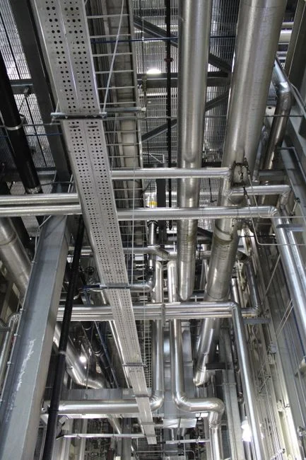
Portland industrial real estate inside the urban growth boundary tends to put water-treatment equipment into existing shells — basements, mezzanines, or purpose-built side rooms next to a tool bay. That drives three real constraints: ceiling height, floor loading, and crane access. The dissolved air flotation system catalog covers 4–300 m³/h across 13 standard models, with single-skid designs at flows ≤66 GPM (~15 m³/h) and a two-skid modular layout above 66 GPM. The COMPACT DAF layout, a low-profile cross-flow design, fits existing fab shells where headroom is under ~3 m (per SigmaDAF product family, 2026-04).
Lamella clarifier footprint at equivalent TSS load is typically 30–50% smaller than an equivalent DAF, but that advantage shrinks once a coagulation tank and mix tube are added upstream. For a Portland retrofit where the floor plan is fixed, the realistic comparison is total skid envelope including chemical conditioning, not just the clarifier body. A double-stacked lamella in a tall but narrow bay can sometimes win on footprint; a single low-profile DAF wins more often on installation labor because the unit is pre-assembled and PLC-controlled.
2026 Cost and Operating Considerations
CAPEX for DAF scales with skid size, material (304SS is the catalog default; 316SS and polypropylene add roughly 20–40% to the vessel cost for fluoride service), and whether the unit is a single skid or a two-skid modular configuration. OPEX is driven by the saturator recycle pump, the air compressor, and the coagulant/polymer dose, which on Portland fab streams typically runs 10–30 mg/L of FeCl₃ or PAC plus 1–5 mg/L of anionic polymer. Lamella OPEX is materially lower on energy (no saturator, no recycle pump), but sludge-handling cost is higher because the underflow is less consolidated than DAF float.
Well-controlled floc chemistry can reduce coagulant consumption on lamella trains by up to 30% compared with a comparable DAF train (per HydropureWater product data, 2026), but that saving rarely closes the gap on a sub-stream that DAF simply removes better. Either way, downstream sludge dewatering is required, and a plate and frame filter press sized to 18–25% dry solids is a reasonable baseline for both clarifier effluents. Coagulant and polymer delivery should be specified with an automatic chemical dosing system tied to a flow-proportional signal so that 40 CFR Part 468 and BES limits are tracked in real time rather than at end-of-day composite sampling. Engineers scoping a broader zero-liquid-discharge or hybrid train around the same sub-streams can read the chip fab wastewater ZLD hybrid system design and the microelectronics high-salinity wastewater treatment blueprint for downstream context.
Frequently Asked Questions
Which is better for CMP slurry wastewater — DAF or a lamella clarifier?
DAF. CMP slurry contains colloidal silica or ceria at sub-10 µm particle size and near-neutral density, which settles poorly in a lamella pack. DAF microbubble flotation (30–50 µm bubbles) reliably lifts the flocculated fraction and achieves 85–95% TSS removal when paired with coagulation/flocculation (HydropureWater field data, 2026).
What permits apply to a Portland semiconductor fab discharging to BES?
Portland fabs discharging to the Columbia Boulevard plant need an Oregon DEQ NPDES permit for industrial wastewater plus a City of Portland BES industrial pretreatment permit, which enforces 40 CFR Part 468 categorical standards. Local limits typically include pH 5–11 and TSS <50 mg/L on a
Frequently Asked Questions
Is DAF better than a clarifier for semiconductor wastewater in Portland?
Dissolved Air Flotation (DAF) is generally superior for semiconductor wastewater in Portland due to the high density of low-specific-gravity particles typical of CMP waste, which often resist gravity settling. While clarifiers rely on Stokes' Law for sedimentation, DAF uses micro-bubbles to float hydrophobic particles, providing a smaller footprint—essential for the high-cost real estate in the Pacific Northwest—and achieving higher surface overflow rates (SOR) of 2 to 4 gpm/ft² compared to 0.5 to 1.0 gpm/ft² for conventional clarifiers.
What removal efficiency does DAF achieve on CMP slurry?
When properly dosed with cationic coagulants and anionic flocculants, DAF systems consistently achieve Total Suspended Solids (TSS) removal efficiencies of 95% to 99% for CMP slurry. These systems effectively manage sub-micron silica particles, often reducing influent TSS concentrations of 500–2,000 mg/L down to discharge levels below 50 mg/L, depending on the specific abrasive chemistry and surfactant loading.
Does a Portland semiconductor fab need 40 CFR Part 468 pretreatment?
Yes, any semiconductor manufacturing facility in the Portland area discharging to a Publicly Owned Treatment Works (POTW) must comply with 40 CFR Part 468 (Metal Finishing Point Source Category). This regulation mandates strict pretreatment standards for pollutants including arsenic, copper, lead, and total toxic organics (TTO), requiring DAF or clarifier systems to be integrated into a broader wastewater treatment train that includes pH adjustment, metal precipitation, and potentially advanced oxidation.
When is a lamella clarifier acceptable for fab wastewater?
A lamella clarifier is acceptable when the primary waste stream consists of high-density inorganic solids, such as metal hydroxides generated from precipitation tanks, rather than low-density CMP slurries. They are preferred in space-constrained fab environments where the specific gravity of the suspended solids exceeds 1.5, allowing for efficient plate-settling without the recurring operational costs of air saturation systems or sludge skimmers required by DAF units.
What flow rate should I size a DAF for at a 300 mm wafer fab?
For a standard 300 mm wafer fabrication plant, DAF systems should be sized based on total facility effluent, typically ranging from 500 to 1,500 gallons per minute (gpm) to account for peak CMP tool wash-down cycles. Engineers must size the DAF unit for a minimum hydraulic retention time (HRT) of 20 to 30 minutes and provide a 20% surge capacity buffer to handle the intermittent, high-volume discharges characteristic of automated wafer polishing processes.