
How Meridian Petroleum Wastewater Differs From Other Industrial Streams
For Meridian petroleum facilities in 2026, dissolved air flotation (DAF) is the stronger primary oil and grease removal step, typically achieving 95% FOG removal versus roughly 70% for a gravity clarifier on the same stream. Clarifiers remain more cost-effective when the dominant load is heavy sediment rather than free or emulsified oil. Most Meridian refineries benefit from a hybrid DAF-after-clarifier train to satisfy 40 CFR Part 435 and local POTW discharge limits.
The wastewater profile downstream of a Meridian refinery or tank-farm separator is unusually heterogeneous. Free oil, emulsified oil, dissolved organics, and suspended solids all coexist, with residual oil concentrations typically falling between 50 and 5,000 mg/L after an API or CPI separator has done its primary work (S3). That range, not a single number, is what defines the polishing-stage decision. The DAF-vs-clarifier question is fundamentally a density-separation question: free and emulsified oil droplets float, while sand, scale, rust, and other heavy grit settle. A refinery that tries to force both fractions through a single unit is choosing the wrong tool for at least one of them.
Most Meridian facilities already operate an API or CPI separator upstream; that separator removes the bulk of free oil and is not what is being replaced. The DAF or clarifier under evaluation is the secondary, polishing step that protects the downstream biological system or the final effluent outfall. The same separation logic applies to produced water from any E&P activity in Mississippi, where the regulatory and physical drivers are comparable. For more on the mechanism comparison that follows this regulatory framing, see the pressure flotation vs alternatives decision guide.
What 40 CFR Part 435 and Meridian's Local Limits Require
40 CFR Part 435 (the Oil and Gas Extraction Point Source Category) sets the federal floor for refinery discharges, with conventional pollutant limits covering oil and grease, total suspended solids (TSS), and chemical oxygen demand (COD). Mississippi DEQ and the local Meridian POTW pretreatment ordinance layer additional, tighter limits on top of the federal rule. In practice, a Meridian refinery or tank farm discharges to a POTW with a daily maximum oil and grease limit of 10–15 mg/L and a TSS ceiling around 30 mg/L; surface discharges under state NPDES permits run tighter still. Those numbers are the targets the polishing step must hit, not aspirational goals.
The gap between influent and effluent is where the technology choice becomes decisive. Starting from a separator effluent of several hundred mg/L oil, the polishing unit must deliver a 90%+ reduction to land inside the 10–15 mg/L band. A DAF unit reliably delivers >95% FOG removal (S3); a conventional clarifier on the same stream delivers closer to 70% (S1). That 25-point spread is the difference between a clean compliance event and a non-compliance event on a refinery's monthly discharge monitoring report.
A clarifier alone, on a free-oil stream with no chemical conditioning and no downstream polishing, is rarely sufficient to meet Meridian's effluent oil and grease limits. Even a well-operated clarifier leaves too much emulsified oil in the overflow to satisfy a 10–15 mg/L daily maximum without a follow-on stage. This is why most Meridian facilities evaluating a 2026 capex are not choosing between DAF and a clarifier as mutually exclusive options; they are choosing the order of a two-stage train. The federal rule sets the floor; the local ordinance sets the ceiling; the technology has to fit between them.
How DAF and Clarifiers Each Treat Oily Wastewater
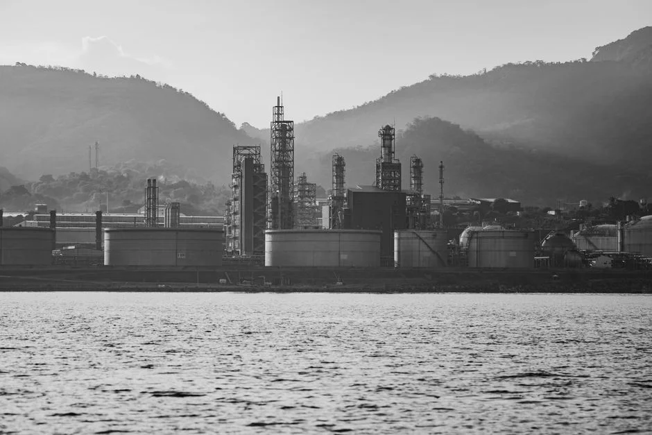
A gravity clarifier relies on Stokes' law settling: heavier solids drop to the bottom under quiescent conditions and are raked to a central sludge hopper, while lighter material is supposed to overflow as clarified effluent. The mechanism works well for dense, readily settleable grit and for sludge thickening, but it is sensitive to influent temperature, density currents from influent jets, and short-circuiting in shallow basins. On an oily stream, free oil will eventually float to the top of a clarifier, but emulsified oil droplets in the 10–100 µm range settle too slowly to be captured at typical hydraulic residence times (S3).
A DAF unit inverts the separation vector. Pressurized recycle water at 4–6 bar is saturated with air in a packed or venturi saturator, then released through a pressure-reduction valve into the flotation tank. The sudden pressure drop precipitates a cloud of 10–100 µm microbubbles that attach to oil droplets and flocculated solids, lifting them at rise velocities of 5–15 m/h (S3). The buoyant sludge blanket is skimmed from the surface, and clarified effluent is withdrawn from below.
Three operating parameters define whether a DAF performs to spec. The air-to-solids (A/S) ratio must be held in the 0.005–0.06 mL air per mg solids band — too little air starves the float, too much wastes energy and disrupts the blanket. The recycle rate is typically 10–50% of forward flow, with most municipal and industrial systems running 20–40% (S3). And hydraulic loading rates of 5–30 m³/m²·h are standard, with high-rate DAF (HR-DAF) configurations using inclined plate packs to push up to 40 m³/m²·h in a much smaller footprint (S3).
On a properly conditioned oily stream, DAF achieves >95% FOG removal and 40–60% BOD reduction before biological treatment (S3), which matches the 95% vs 70% head-to-head data point used in generic industrial comparisons (S1). DAF is also less sensitive to cold influent and to emulsified oil than sedimentation, a meaningful advantage for outdoor Meridian tank-farm applications where winter temperatures drop the clarifier's effective settling velocity without affecting bubble attachment. For a deeper dive on the chemistry side, the polymer overdosing troubleshooting guide covers how to keep floc strength where DAF needs it.
Side-by-Side Comparison: DAF vs Clarifier for Oily Streams
The table below captures the decision-grade parameters a Meridian procurement manager screens against. Numbers reflect typical operating ranges for refinery and tank-farm applications, not lab benchmarks.
| Parameter | Dissolved Air Flotation (DAF) | Gravity Clarifier (incl. Lamella) |
|---|---|---|
| Oil & FOG removal efficiency | >95% (S1, S3) | ~70% on oily streams (S1) |
| Typical FOG effluent | 5–20 mg/L with chemical conditioning | 30–80 mg/L on free-oil feed |
| Hydraulic loading rate | 5–30 m³/m²·h standard; up to 40 m³/m²·h HR-DAF (S3) | ~1–3 m³/m²·h conventional; 20–40 m/h surface loading for lamella plates |
| Sludge solids content | 2–6% (S3) | 0.5–2% (dilute) |
| Footprint for 100 m³/h | ~3–6 m² (HR-DAF) | ~35–100 m² (conventional) or 8–15 m² (lamella) |
| Energy demand | Moderate (recycle pump + air compressor; VFD options cut kWh) | Low (rake drive only) |
| Chemical demand | Coagulant + flocculant typical; 5–15% of opex (S3) | Minimal unless used as primary oil step |
| Sensitivity to emulsified oil | Low — bubble attachment captures 10–100 µm droplets | High — emulsified oil does not settle |
| Sensitivity to cold influent | Low | High — viscosity slows settling |
| Capex / opex (relative rank) | Higher capex, comparable opex once chemicals are included | Lower capex, lower opex if used on the right stream |
| Upstream API/CPI requirement | Tolerates higher residual oil; still recommended | Required for free-oil protection; can be overwhelmed |
| Best fit | Free and emulsified oil, compact footprint, cold or variable influent | Heavy sediment and grit, low-cost operations, large available footprint (S1, S3) |
Matching Technology to Meridian Influent Scenarios
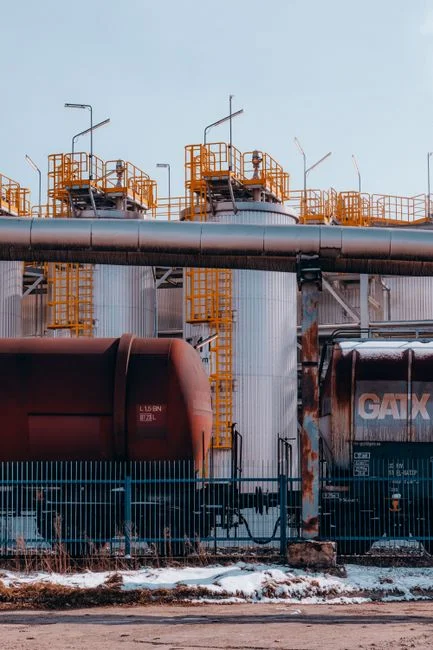
The decision is rarely abstract. The table below maps the three most common Meridian influent profiles to a recommended configuration, drawn from the operating ranges above.
| Scenario | Flow & Load Profile | Recommended Configuration | Rationale |
|---|---|---|---|
| A — Small Meridian refinery | 50–200 m³/h, moderate oil (200–800 mg/L post-API), limited footprint, variable production schedule | HR-DAF with plate packs at up to 40 m³/m²·h (S3) | Compact footprint, >95% FOG removal, tolerates emulsified oil from desalter upsets |
| B — Tank farm or re-refinery | 100–500 m³/h, high grit and sediment from truck unloading and tank bottoms, plus free and emulsified oil | Primary lamella clarifier → DAF polish (S1 confirms hybrid as common) | Clarifier protects DAF from grit blinding; DAF polishes emulsified oil to discharge limits |
| C — Produced water / oil-field services near Meridian | Highly variable flow, 50–5,000 mg/L oil swings, short-duration or pilot projects, remote or temporary sites | Trailer-mounted mobile DAF (S5), single-day deployment, frac-tank-style trailer 47'–52' long | Rapid mobilization for produced water, frac flowback, or surge capacity during turnarounds |
Most Meridian refineries sit between scenarios A and B: a stable oily base load with episodic sediment pulses from tank cleaning and desalter upsets. That is the profile that justifies a hybrid train rather than a single-unit answer. For a parallel regional comparison, the Nashville petroleum DAF vs clarifier guide applies the same matrix to a similar refining footprint, and the Schenectady petroleum DAF vs clarifier guide covers a colder-climate analog where DAF's temperature insensitivity is the deciding factor.
Capital, Operating Cost and Footprint Trade-offs in 2026
Clarifiers carry lower upfront capital and lower ongoing operating cost than a comparably rated DAF, but they require significantly more tank volume to hit the same oil-removal target on an oily stream (S1, S3 implied by the 5–30 m³/m²·h DAF range vs ~1–3 m³/m²·h for a conventional clarifier). On a constrained Meridian site where tank-farm real estate is already spoken for, that footprint delta often reverses the capex comparison once land cost, civil work, and structural steel are priced in. Lamella clarifiers narrow the gap by trading tank depth for plate area, but they still do not match HR-DAF's hydraulic loading rate on oily feed.
DAF energy use is dominated by the recycle pump and the air compressor. Modern VFD-driven saturators paired with packed-tower designs routinely achieve 80–95% air saturation efficiency (S3), which trims compressor runtime and avoids the oversized-blower problem that penalized first-generation DAF installations. Chemical conditioning is the other opex line: coagulant plus flocculant is typically required on emulsified oil and adds 5–15% to operating cost depending on polymer selection and dose (S3). A well-run jar-testing program is the difference between a 5% chemical opex and a 15% chemical opex on the same stream.
ROI on a DAF upgrade is best framed as avoided cost plus recovered value, not as energy saved. DAF typically pays back through (a) avoided non-compliance events under 40 CFR Part 435 and Mississippi DEQ limits, (b) recovered oil skimmed for resale rather than paying hauling and disposal, and (c) avoided footprint cost vs an equivalently rated clarifier on oily streams. For facilities sizing the equipment, the DAF system covers 4–300 m³/h across 13 standard models, while the HydropureWater high-efficiency sedimentation tank covers the clarifier or lamella side of the hybrid train.
How HydropureWater Configures a Meridian DAF or Clarifier Train
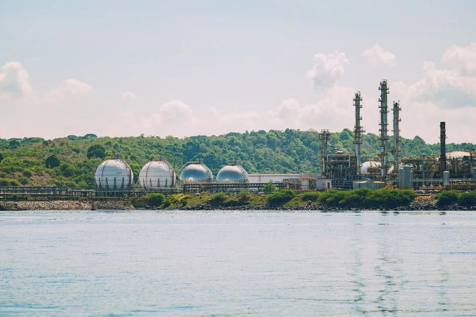
For the DAF side of the train, the DAF system ships in 13 standard models from 4 to 300 m³/h, with micro-bubble flotation, an automatic surface skimmer, and a saturator package sized to the selected hydraulic loading. DAF units have been specified into petrochemical applications for free-oil and emulsified-oil polishing downstream of API/CPI separators, which matches the Meridian retrofit case directly.
For the clarifier side, the HydropureWater high-efficiency sedimentation tank runs at 20–40 m/h surface loading with internal sludge recirculation, which lifts clarifier hydraulic loading into DAF-adjacent territory and reduces chemical demand by roughly 30% compared to a conventional basin — useful as the primary stage in scenario B where grit and sediment would otherwise blind a DAF.
Both technologies are typically paired with the automatic chemical dosing system for coagulant and flocculant feed, since jar-test-optimized polymer programs are what hold the A/S ratio and floc strength in the operating window described above. The dosing skid is sized to the recycle and forward flows and is the lowest-risk package to add when commissioning either unit on a Meridian oily stream.
Frequently Asked Questions
DAF or clarifier for petroleum wastewater in Meridian, United States: which should factories choose in 2026?
For most Meridian refineries and tank farms in 2026, DAF is the stronger primary oil and grease removal step, delivering >95% FOG removal versus roughly 70% for a gravity clarifier on the same separator effluent (S1, S3). The right answer is a hybrid train — clarifier for grit and sediment, DAF for oil polishing — when both fractions are present.
What oil loading can a DAF handle after an API or CPI separator?
Modern DAF systems are routinely specified for oil concentrations from 50 to 5,000 mg/L downstream of an API or CPI separator (S3). The saturator, A/S ratio, and polymer program are sized to the upper end of that band; the lower end is straightforward with no chemical conditioning on free oil.
Does 40 CFR Part 435 require DAF for refinery wastewater?
40 CFR Part 435 sets the federal pollutant limits for oil and grease, TSS, and COD on refinery discharges but does not mandate a specific technology. In practice, hitting Meridian's local POTW limits of 10–15 mg/L oil and grease and ~30 mg/L TSS typically requires the >95% FOG removal a DAF delivers, often paired with biological polishing.
Can a mobile DAF be deployed at a Meridian facility for produced water or turnarounds?
Yes. Trailer-mounted mobile DAF units are designed to be delivered and brought online within a single day, with frac-tank-style trailers roughly 47'–52' long requiring only a level surface, power, and piping connections (S5). They are well suited to produced water treatment, frac flowback, and surge capacity during refinery turnarounds.