Why Plastics and Rubber Wastewater Behaves Differently
Plastics and rubber effluent under NAICS 326 / SIC 30 is dominated by contaminant families that do not behave like a typical industrial stream. Uncured SBR, NBR, and EPDM latex enters the drain as buoyant emulsion droplets with specific gravity below 1.0; PVC and polyethylene fines arrive as sub-100 μm granules; phthalate and adipate plasticizers, along with paraffin and silicone mold-release oils, contribute 50–1,500 mg/L of FOG; and cleaning-tank caustic swings pH across a 4–11 band during wash cycles. Calcium carbonate, talc, and regrind from edge-trim add a dense-grinding fraction on the same line, so a single effluent pipe can carry particles with specific gravities both above and below water (per EPA Process Design Manual, S1, Section 1.2).
TSS routinely lands between 200 and 2,500 mg/L in compounding, extrusion, and molding facilities, with the largest fraction sitting in the supracolloidal and settleable size bands (1–100 μm and >100 μm) defined in S1 Chapter 1. Those bands respond very differently to gravity versus flotation: supracolloidal polymer and latex particles resist Stokes-law settling because their effective density is near 1.0 and their drag coefficient is high, while a gravity clarifier will reliably drop the dense regrind and filler. The same influent challenges each unit in a different direction, which is why a one-size-fits-all selection rarely fits a NAICS 326 line.
How a DAF Unit Actually Treats This Stream
Dissolved air flotation works in four steps: a sidestream of effluent is saturated with air at 4–6 bar in a pressure vessel; the pressurized stream is depressurized through a needle-valve or nozzle, releasing a dense cloud of 30–50 μm microbubbles (SigmaDAF/Clearwater, S4); those bubbles contact chemically conditioned floc and attach to hydrophobic or buoyant particles; a paddle skimmer then removes the floated layer while heavier settleables drop to a bottom auger (S1 Section 7.8; S4).
EPA Table 7-4 (S1) lists DAF hydraulic loading at 5–25 m/h and an air-to-solids ratio of 0.005–0.060 lb air per lb solids for suspended-solids applications. Those ranges are roughly an order of magnitude higher than the 1–2.5 m/h overflow rate that EPA Table 7-2 allows for a primary clarifier, which is why a DAF tank of the same throughput is typically 60–80% smaller in plan area. For a Plymouth-scale plant in the 4–300 m³/h band, the HydropureWater DAF system spans 13 standard models that map directly onto that envelope, so sizing stays inside the EPA-validated window without pilot work in most cases.
How a Gravity or Lamella Clarifier Treats This Stream
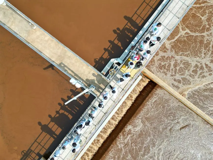
A primary clarifier is a quiescent tank — rectangular or circular — with an inlet stilling zone, a launder-weir outlet, and a sludge hopper. Per EPA Section 7.2–7.5, design turns on overflow rate (1–2.5 m/h), detention time (1.5–2.5 h), and weir loading, all of which assume particles dense enough to reach the floor before short-circuiting carries them to the outlet. Buoyant latex and plasticizer oils tend to form a scum blanket that has to be skimmed separately, and wash-water pH swings destabilize the floc blanket between batches.
A lamella clarifier replaces the single large settling zone with a stack of inclined plates at 55–60°, multiplying the effective surface area inside the same footprint. EPA Section 7.9 notes that steeply inclined tubes raise allowable loading by a factor of 5–10 versus a conventional tank; the HydropureWater high-efficiency lamella clarifier publishes a 20–40 m/h surface loading range on that principle. Both clarifier styles still rely on coagulation chemistry from EPA Chapter 4 — typically a cationic polymer paired with alum or ferric for plastics effluent — to convert supracolloidal fines into a settleable floc, which is the variable that determines whether a clarifier can hit a 250 mg/L TSS permit.
DAF vs Clarifier: Head-to-Head Comparison for Plastics and Rubber Plants
The table below anchors each row in an EPA Process Design Manual or vendor figure, providing a defensible basis for permit or capex review. The HydropureWater equipment links in the rows below are the same products introduced in the two mechanism sections.
| Parameter | Gravity / Lamella Primary Clarifier | Dissolved Air Flotation (DAF) |
|---|---|---|
| TSS removal, primary stage | 60–90% (EPA S1, Chapter 7 range) | 80–95% (EPA S1, Section 7.8; vendor field data 2026) |
| FOG removal | 50–70% (scum-skim dependent) | >90% typical (S4) |
| Hydraulic / surface loading | 1–2.5 m/h conventional; 20–40 m/h lamella | 5–25 m/h (EPA Table 7-4) |
| Air-to-solids ratio | Not applicable | 0.005–0.060 lb air / lb solids (EPA Table 7-4) |
| Footprint for ~50 m³/h | Circular clarifier typically 8–12 m diameter; concrete tankage | Mobile trailer 47'6" x 8'6" small or 51'7" x 8'6" large (S2); skid footprint indoors |
| Chemical demand | Cationic polymer + alum/ferric; coagulant-driven | Cationic polymer + alum/ferric; often lower polymer dose due to bubble assist |
| Startup time | Hours to establish sludge blanket | ~1 hour to saturate and skim (S2) |
| Sensitivity to flow spikes | High — short-circuiting resuspends floc | Moderate — hydraulic loading range is wide |
| Low-density latex (SG < 1.0) | Poor — particles report to scum, not sludge | Strong — bubbles attach and lift |
| Dense regrind / filler (SG > 1.2) | Strong — settles readily | Adequate with bottom auger; not the primary lift path |
| Reference design product | Lamella clarifier (20–40 m/h) | DAF (4–300 m³/h) |
The lamella clarifier pushes surface loading into the 20–40 m/h band without DAF chemistry, which is useful when influent is mostly dense, non-buoyant regrind or filler at a steady rate. When low-density latex or FOG drives the load, DAF provides higher removal efficiency and a smaller footprint; when both fractions appear on the same line, a DAF primary with a lamella polishing stage (the FPBC architecture in S4) captures the full range.
Plymouth-Specific 2026 Decision Factors: Discharge Limits, Permits, and Footprint
Plastics and rubber manufacturing sits under NAICS 326 / SIC 3081/3089, which is regulated through the 40 CFR Part 414 (organic chemicals, plastics, and synthetic fibers) and Part 433 (metal finishing) pretreatment categories, enforced locally by the Plymouth POTW sewer-use ordinance. For 2026, typical local discharge limits applied to these SIC codes run TSS ≤ 250–300 mg/L, FOG ≤ 100 mg/L, and pH 6–10. A clarifier alone can usually meet 250 mg/L TSS on dense regrind, but it struggles to push FOG below 100 mg/L because the buoyant fraction is precisely what gravity rejects last.
Space is the second constraint on a Plymouth plant. Many injection-molding and extrusion sites sit inside older buildings where new concrete tankage is impractical, so a plug-and-play skid is the realistic path. SigmaDAF's Compact DAF (S4) ships as a single skid at flows ≤ 66 GPM (≈ 15 m³/h) and scales to a two-skid modular assembly above that, with chemical conditioning, sensors, and a PLC on the same frame. The WesTech mobile trailer (S2) covers temporary or supplemental duty at 47'6" x 8'6" or 51'7" x 8'6" — useful when a clarifier is being refurbished or a permit clock is running.
Decision Tree: Which Should Your Plymouth Plant Choose?
Three diagnostic questions resolve most capex cases for NAICS 326 plants in Plymouth.
- Is FOG or free latex > 100 mg/L, or do your solids have specific gravity < 1.0? If yes, specify a DAF as the primary unit. The HydropureWater DAF system covers 4–300 m³/h with 13 models, mapping directly onto EPA Table 7-4 hydraulic loadings. CAPEX band: $90,000–$250,000 installed for skid-mounted units in the 10–50 m³/h range, based on HydropureWater field data (2026).
- Is TSS dominated by dense, non-floating regrind or filler at a near-steady flow with little FOG? If yes, specify a lamella clarifier. The HydropureWater high-efficiency lamella clarifier runs 20–40 m/h surface loading with no air-saturation equipment, which keeps the chemical and O&M budget lower. CAPEX band: $40,000–$120,000 for a comparable flow rate (HydropureWater field data, 2026).
- Are both fractions present, or does the line swing between wash-down and process water? Specify a DAF primary with a lamella polish — the architecture SigmaDAF calls the FPBC. The DAF carries the buoyant load and the lamella pack catches fines that escape the float, holding TSS comfortably under 250 mg/L during a wash cycle. Use a 2024-vintage DAF design engineering guide to validate the hydraulic profile, and compare sizing against the 2025 primary clarifier specifications and design parameters benchmark to keep both stages inside their design envelopes. For sister-industry context, see this 2026 DAF vs clarifier for chemical-plant wastewater comparison.
If your facility discharges to a POTW with an active FOG limit ≤ 100 mg/L or a TSS limit ≤ 250 mg/L, a clarifier-only path will usually need a polishing step anyway, and the marginal cost of moving to a DAF primary is recovered in lower polymer dose, smaller tankage, and faster startup.
Frequently Asked Questions
What TSS and FOG removal can a DAF realistically hit on plastics or rubber effluent?
On chemically conditioned NAICS 326 effluent, a DAF typically removes 80–95% of TSS and >90% of FOG, per EPA Process Design Manual Section 7.8 ranges and SigmaDAF field performance (S4). A primary clarifier typically removes 60–90% TSS but only 50–70% FOG because buoyant latex and plasticizer oils do not settle.
Are plastics and rubber plants regulated under 40 CFR Part 414 or 433 in Massachusetts?
Plastics and rubber manufacturing falls under NAICS 326 / SIC
Frequently Asked Questions
Should a plastics factory use DAF or a clarifier for wastewater treatment?
The choice depends on the specific gravity and particle size of the suspended solids. Dissolved Air Flotation (DAF) is preferred for plastics manufacturing because plastic particles and polymers often have a specific gravity close to or less than water, making them resistant to settling. DAF utilizes micro-bubbles to lift these low-density particles to the surface for skimming.
Gravity clarifiers are more effective for dense, inorganic fillers or heavy mineral-based additives common in some rubber processing. If the wastewater stream contains a high concentration of buoyant plastic fines or oils, DAF is the industry standard to ensure efficient separation and prevent carryover into downstream biological treatment processes.
How effective is DAF for removing latex and plasticizer oil from rubber plant wastewater?
DAF is highly effective for latex and plasticizer removal, typically achieving 85% to 95% removal efficiency when paired with appropriate coagulation and flocculation chemistry. Latex particles, which are essentially colloidal emulsions, require charge neutralization and polymer bridging to destabilize the emulsion before micro-bubbles can attach and float the solids.
Plasticizer oils, which are often hydrophobic and lighter than water, are readily captured by the air-bubble interface in a DAF unit. Proper hydraulic loading rates, typically maintained between 1.0 and 2.5 gallons per minute per square foot (gpm/ft²), are critical to preventing shear and ensuring that the oily sludge blanket remains stable during the skimming process.
What is the typical TSS removal for DAF versus a gravity clarifier?
In plastics and rubber applications, a properly operated DAF system typically achieves 80% to 95% Total Suspended Solids (TSS) removal, depending on the chemical pretreatment dosing. Because many plastic waste streams consist of lightweight polymers, gravity clarifiers often struggle with these materials, frequently yielding TSS removal rates as low as 40% to 60% without massive chemical dosing to increase particle mass.
While a gravity clarifier can achieve 90%+ TSS removal for heavy, inorganic silt or sand, it is rarely suitable for the light, hydrophobic polymers prevalent in modern plastics compounding. DAF systems provide a more consistent effluent quality for these specific materials, often reducing TSS to below 50 mg/L in pre-treatment applications.
What 2026 discharge limits apply to NAICS 326 plastics manufacturers in Massachusetts?
NAICS 326 facilities discharging to a Publicly Owned Treatment Works (POTW) in Plymouth must comply with local sewer use ordinances and federal categorical pretreatment standards under 40 CFR Part 463. As of 2026, typical discharge limits for these facilities include a pH range of 5.0 to 12.0, and strict prohibitions on oil and grease, typically capped at 100 mg/L to prevent sewer interference.
Facilities discharging directly to surface waters must adhere to National Pollutant Discharge Elimination System (NPDES) permits, which often set stringent MassDEP-approved limits for Total Petroleum Hydrocarbons (TPH) and specific volatile organic compounds (VOCs). Operators must consult their individual permit for specific mass-loading limits, as these are increasingly tightened to meet 2026 state water quality standards for Massachusetts coastal watersheds.
Can a lamella clarifier replace a DAF unit in a plastics compounding plant?
A lamella clarifier can only replace a DAF unit if the plastic waste particles have a specific gravity significantly higher than 1.05 and are non-emulsified. Because lamella clarifiers rely on settling plates to reduce the required footprint, they are physically incapable of removing the buoyant resins, films, and oils that characterize most compounding plant wastewater.
If the compounding process involves heavy mineral fillers like calcium carbonate or talc, a lamella clarifier may be used as a primary solids separator. However, for most plastics compounding facilities, replacing DAF with a lamella clarifier will result in significant solids carryover and potential non-compliance with effluent oil and grease limits, as the buoyant fraction will bypass the settling plates entirely.