
Why Wabash Fabricated Metals Plants Are Re-Evaluating Oil Removal in 2026
Wabash, Indiana sits at the crossroads of US-24 and IN-15 in a county where stamping presses, CNC machining cells, cold-heading lines, and e-coat/powder-coat operations generate the majority of the local industrial wastewater load. The streams those shops send to the floor drain carry tramp oil from stamping sumps, broken cutting-fluid emulsions from machining, drawing compounds from cold forming, and phosphating rinse water from coating lines. A typical Wabash plant sees free oil concentrations swing from 30 mg/L during a normal production shift to several hundred mg/L during a coolant batch dump, with total suspended solids (TSS) in the same proportional range. That variability is the operational pain driving the 2026 re-evaluation.
The regulatory pressure is now concrete. The Wabash POTW enforces 40 CFR Part 433 metal-finishing categorical pretreatment standards, which set a daily-maximum oil & grease ceiling of 52 mg/L, a total metals ceiling of 2.61 mg/L, and a TSS ceiling that drops as low as 31 mg/L depending on the regulated subcategory. Surcharges for oil & grease and TSS at the Wabash treatment plant increased for the 2026 rate year, meaning a single non-compliant batch now shows up directly on the operating budget. The 40 CFR Part 433 limits sit under the umbrella of 40 CFR Part 403 general pretreatment rules, which gives the local POTW the authority to enforce categorical ceilings. For a plant engineer, the practical question is "which separator technology hits Part 433 consistently at our flow rate?" The answer depends on flow window, free-oil loading, and operator attention, which is the framework used throughout this fabricated metals pretreatment compliance guide.
How a DAF Actually Separates Oil and Solids in a Metalworking Stream
A dissolved air flotation (DAF) unit removes contaminants by attaching 30–50 micron micro-bubbles to chemically conditioned floc and floating the agglomerate to the surface, where a paddle skimmer strips it off (per Clearwater Industries/SigmaDAF technical literature, 2026-04). The train starts with coagulation—typically polyaluminum chloride (PAC) at 50–150 mg/L or alum for metal-finishing streams—followed by a flocculation stage where anionic polymer builds a settleable floc. The flocculated stream then enters a pressurized saturation tank held at 60–80 psig, where dissolved air is held in solution. A needle valve or proprietary breakout valve downstream releases that pressure, and the dissolved air comes out of solution as a dense cloud of micro-bubbles that nucleate on the floc surface. The combined particle-bubble density drops below water, and the floc rises in roughly 15–25 minutes of hydraulic residence time. These mechanical stages bridge the gap between variable raw influent and consistent discharge quality.
The reason a DAF dominates over a gravity clarifier on free-oil streams is straightforward: neutrally buoyant and slightly heavier-than-water oil droplets will not rise in a quiescent clarifier, but they will lift when a micro-bubble attaches. For Wabash plants that see tramp oil, drawing compounds, and partially broken emulsions in the same shift, that capability closes the gap between a 150 mg/L influent and a 30 mg/L effluent. Four DAF configurations cover the Wabash flow window: a compact single-skid unit at or below 66 GPM, a high-profile FPBC with lamella pack for medium solids, a cross-flow FPHF for high flow, and a turnkey COMPACT unit with PLC-controlled chemical dosing and skimmer speed (per Clearwater Industries, 2026-04). Standard wetted material is 304SS; 316SS is specified for chloride-bearing coolants, and polypropylene is used for acidic phosphating rinse water. For Wabash machining shops running synthetic coolants with chloride inhibitors, the material selection determines tank life. A packaged HydropureWater DAF system covers the 4–300 m³/h band that maps directly to the 30–80 GPM typical of Wabash facilities.
How a Lamella Clarifier Handles the Same Wastewater Differently
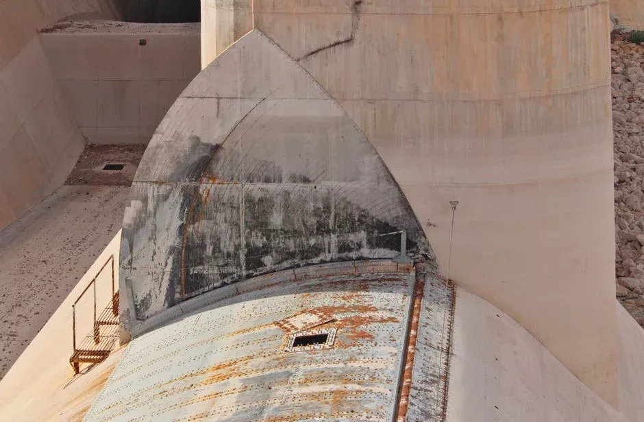
A lamella clarifier uses a stack of plates inclined at 60° to multiply the effective settling area inside a small footprint. The effective area equals the projected plate area times the cosine of the inclination angle, and sludge slides down the plate face into a hopper while clarified water rises through the plate pack. Coagulant is dosed upstream, often with a sludge-recycle loop that builds a floc blanket and improves capture. Surface loading rates of 20–40 m/h are typical for this geometry, and the design uses up to 30% less coagulant than a conventional clarifier handling the same TSS load (per HydropureWater lamella product specification, 2026). These units provide high-efficiency sedimentation for specific, lower-variability waste streams.
Where lamella wins is a narrow but real slice of the Wabash market: low free-oil influent (typically under 30 mg/L), steady-state flow without coolant dumps, modest footprint tolerance, and an operator who is not a full-time wastewater technician. A stamping rinse line with consistent flow and a working oil skimmer upstream is the canonical fit. The failure mode that pushes a Wabash plant away from lamella is cold weather. Wabash winter temperatures drop the kinematic viscosity of free oil and the underlying wastewater simultaneously, slowing the rise rate of oil droplets in a quiescent zone. Once influent oil climbs above ~50 mg/L or the flow exceeds 30 GPM with swings, a lamella clarifier will not reliably meet the 40 CFR Part 433 52 mg/L oil & grease ceiling. A HydropureWater lamella clarifier remains the right call for that narrow band, but the DAF threshold sits much lower than most plant engineers expect.
DAF vs Clarifier for Wabash Fabricated Metals: Decision Matrix
The selection tool below distills removal efficiency, footprint, residence time, and capital range into a head-to-head comparison for the 30–80 GPM Wabash operating window. Removal percentages are steady-state operating ranges drawn from manufacturer performance data and standard industrial wastewater engineering practice (per Clearwater Industries, 2026-04; per HydropureWater field data, 2026). Capital ranges are order-of-magnitude installed US 2026 figures and exclude building or civil work.
| Parameter | Lamella Clarifier | Dissolved Air Flotation (DAF) | Best Wabash Fit |
|---|---|---|---|
| Free-oil removal | 40–60% | 80–95% | DAF: stamping + machining coolant mix above 50 mg/L oil |
| TSS removal | 60–80% | 85–95% | DAF: phosphating rinse and coating line overflows |
| FOG removal | 50–70% | 85–95% | DAF: parts washer effluent with surfactant emulsions |
| Hydraulic residence time | 60–90 min | 15–25 min | DAF: smaller equalization tank required |
| Footprint per 50 GPM | ~40–55 ft² | ~25–35 ft² | DAF: tighter floor space; lamella OK if footprint free |
| CAPEX band (installed, US 2026, 50 GPM) | $35K–$90K | $90K–$220K | Lamella for <30 GPM; DAF for 30–100 GPM |
| OPEX band (chemicals + sludge) | Lower chemical; 1–2% underflow solids | Higher chemical; 3–6% float solids | DAF float dewatered on a plate-and-frame press |
Both technologies fail at the same point: dissolved or emulsified oil below 20 microns in droplet size. That stream needs a chemical break (PAC plus polymer at adjusted pH) before the separator, or a downstream ultrafiltration membrane polish. For Wabash parts-washer effluent carrying surfactant-stabilized emulsions, the DAF should be followed by an MBBR polishing stage for residual COD, not by another clarifier.
When a Wabash Plant Should Skip Both and Use an API Separator First
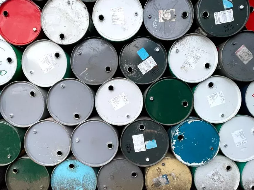
The first separator decision is not DAF-versus-clarifier—it is whether to install a gross oil API separator or corrugated plate interceptor (CPI) upstream of either technology. An API/CPI unit has no moving parts, targets free oil droplets larger than 100 microns, and removes 60–80% of free oil in the influent before any downstream device sees it. The result is a 40–60% reduction in sludge load on the DAF or lamella, which directly extends chemical-dosing intervals and lengthens the time between filter-press cycles. For Wabash shops with a parts washer dump, a stamping press sump, or a centralized floor drain header carrying chip and rag debris, a CPI ahead of the DAF is standard practice. These pre-treatment units protect downstream equipment from heavy debris.
CPI units do not tolerate rags, stringy chips, or wipes, which is why a rotary bar screen is installed on the CPI inlet to protect the plate pack from carryover. Once the CPI has done its work, the downstream DAF or lamella only has to handle emulsified oil, FOG, and fine TSS. Skipping the upstream CPI is the single most common reason Wabash plants see premature DAF float-chamber fouling and polymer demand that exceeds the design basis.
Sizing, Footprint, and CAPEX Reality for a 30–80 GPM Wabash Shop
Translating the decision matrix into flow brackets keeps the conversation grounded: under 30 GPM with low free oil, a lamella clarifier is defensible; 30–100 GPM with variable oil loading points to a packaged DAF; above 100 GPM, a DAF with a parallel plate pack (FPBC configuration) or a two-skid modular DAF is the standard escalation (per Clearwater Industries, 2026-04). For the 30–80 GPM Wabash shop, that means a single-skid DAF or COMPACT unit is almost always the right call, and the 13-model HydropureWater DAF line covering 4–300 m³/h (roughly 18–1,320 GPM) puts the entire Wabash operating band inside standard catalog coverage. Selecting the right capacity ensures compliance without overspending on footprint.
Order-of-magnitude installed CAPEX for US 2026—excluding building work, structural pads, or service utility upgrades—runs $35K–$90K for a packaged lamella clarifier at 50 GPM and $90K–$220K for a packaged DAF in the same flow range. The DAF premium buys the chemical dosing skid, pressurized air system, PLC, and skimmer mechanism that the lamella does not require. The 2-year structural warranty on the tank and aeration skid is a defensible benchmark in vendor negotiations (per VanAire product literature, 2026). Sludge handling differs: DAF float runs 3–6% dry solids and is dewatered on a plate-and-frame filter press to a 25–35% cake; lamella underflow runs 1–2% dry solids and routes to the same press but with longer cycle times. The automatic chemical dosing skid that feeds the DAF is the second line item plant engineers tend to underestimate in their 2026 capex plan—PAC and polymer pumps, calibration columns, and a pH probe are not optional accessories when the POTW is enforcing Part 433.
Frequently Asked Questions
What are the 40 CFR Part 433 oil and grease limits for fabricated metals plants in Wabash?
The metal-finishing category under 40 CFR Part 433 sets a daily-maximum oil & grease ceiling of 52 mg/L and a TSS ceiling that drops to 31 mg/L in the most restrictive subcategories, with total toxic organics and metals subject to additional categorical ceilings (per EPA 40 CFR Part 433).
When is a lamella clarifier acceptable instead of a DAF for a Wabash plant?
A lamella clarifier is acceptable
Frequently Asked Questions
Should a fabricated metals plant in Wabash choose a DAF or a clarifier in 2026?
The choice depends on the specific wastewater composition and the density of the contaminants. Dissolved Air Flotation (DAF) is generally superior for fabricated metals facilities in 2026 if the process stream contains high concentrations of emulsified oils, greases, or light particulates that do not settle readily. DAF systems typically achieve 90-95% removal of suspended solids and oils by floating them to the surface, making them ideal for high-volume coolant and machining waste.
Conversely, a clarifier is more efficient for heavy metal hydroxide precipitation where the particles have a high specific gravity and settle quickly by gravity. If your Wabash facility primarily deals with heavy metal plating waste or inorganic solids, a conventional or lamella clarifier provides a smaller footprint and lower operational energy requirements compared to the pressurized aeration needed for a DAF.
What oil and grease limit does 40 CFR Part 433 set for metal finishing discharge?
Under 40 CFR Part 433, the federal pretreatment standards for metal finishing establish a maximum monthly average limit for Oil and Grease (O&G) of 26 mg/L. Furthermore, the daily maximum limit for Oil and Grease is set at 52 mg/L.
These limits apply to all facilities discharging to a Publicly Owned Treatment Works (POTW). Wabash-based manufacturers must ensure their wastewater treatment system is capable of consistently meeting these thresholds to avoid non-compliance penalties and surcharge fees from local municipal sewer authorities.
Can a lamella clarifier remove tramp oil from a stamping press?
No, a lamella clarifier is not designed to remove tramp oil from stamping press wastewater. Lamella clarifiers rely on gravity to settle dense solids; because tramp oil is often emulsified and lighter than water, it will not settle to the bottom of the plate pack and may instead foul the plates, leading to operational failure.
To remove tramp oil effectively, the wastewater must first undergo chemical demulsification to break the oil-water bond. Once broken, the oil requires a DAF system or an oil-water separator to skim the floating oil from the surface, as mechanical settling alone cannot separate non-aqueous phase liquids from the bulk fluid.
How much does a 50 GPM DAF system cost for a small Indiana metal shop?
For a 50 GPM DAF system, a small metal shop in Indiana should expect a capital expenditure ranging from $65,000 to $120,000 for the skid-mounted unit alone. This price range accounts for standard carbon steel construction, integrated air saturation pumps, and automated surface scrapers.
Total project costs often reach $150,000 to $200,000 when accounting for site-specific requirements, including equalization tanks, pH adjustment systems, chemical feed skids, and professional installation. Prices fluctuate based on material upgrades, such as 304 or 316 stainless steel, which are frequently required to prevent corrosion from acidic metal finishing wastewater.
What chemical dosing is needed before a DAF for coolant wastewater?
Pre-treatment for coolant wastewater typically requires a two-stage chemical process: coagulation followed by flocculation. The initial stage involves dosing a coagulant, such as aluminum sulfate (alum), ferric chloride, or a cationic polymer, at concentrations typically ranging from 50 to 500 mg/L depending on the oil load, to neutralize the surface charges of the emulsified oil droplets.
Following coagulation, a high-molecular-weight anionic flocculant is added at lower concentrations (often 1-10 mg/L) to bridge the neutralized particles into larger, floatable "flocs." Precise pH adjustment, usually to a range of 6.0 to 8.5 using caustic soda or sulfuric acid, is also mandatory to ensure optimal chemical performance and compliance with local discharge standards.