Which Pretreatment Rules Apply to a New Paris Transportation Equipment Plant
Transportation equipment manufacturers near New Paris operate under two layered pretreatment frameworks: EPA's categorical pretreatment standards codified at 40 CFR Part 433 (Metal Products & Machinery) and 40 CFR Part 432 (Metal Finishing), and site-specific local limits imposed by the receiving POTW under 40 CFR 403.5(c). EPA implements PSES (pretreatment standards for existing sources) and PSNS (pretreatment standards for new sources) for 35 of 58 industrial categories; these are technology-based, apply regardless of whether the POTW has an approved pretreatment program, and bind any nondomestic discharger subject to a categorical standard as a categorical industrial user (CIU) (per EPA categorical pretreatment standards page).
For a truck body, trailer, or heavy-equipment assembly plant, Part 433 governs oily wastewater streams from machining, stamping, parts washing, and assembly floor washdown. If the same plant runs plating, anodizing, e-coat, or other surface treatment lines, Part 432 layers additional metal-specific limits on top — chromium, nickel, zinc, lead, and cyanide. The Indiana Department of Environmental Management (IDEM) does not have delegated pretreatment authority for the federal categorical program, so the EPA Region 5 office retains the categorical standards enforcement role for the New Paris area (HydropureWater field data, 2026). On top of that, the local POTW imposes site-specific local limits at the end-of-pipe discharge (the point of connection to the collection system), and these can be numeric or narrative effluent limits, including BMPs (per EPA local limits page).
Compliance is therefore a two-track exercise: the categorical daily-maximum and monthly-average limits in 40 CFR Part 433 Tables 1–3 (and Part 432 where applicable) are non-negotiable, and the POTW's local limits — often stricter on oil & grease, pH excursion tolerance, and slug-load control — must also be met continuously at the discharge point.
What Transportation Equipment Wastewater Actually Contains
Transportation equipment plants generate a mix of oily process wastewater, rinse water, and dilute assembly-floor washdown that does not look like a single uniform stream. The dominant pollutant sources are cutting fluids and machining coolants (high oil content plus emulsifiers and surfactants), parts-wash solvents, phosphating rinse water, E-coat and paint overspray wash water, assembly floor washdown, and boiler blowdown. In plants with plating or surface treatment, spent baths and rinses contribute trace metals (Zn, Ni, Cr, Pb) on top of the oil and TSS load.
Typical raw influent values observed at transportation equipment sites in the Midwest sit at TSS 200–1,500 mg/L, oil & grease 100–2,000 mg/L, and pH 4–11 excursions during batch dumps, with zinc and nickel in the 1–20 mg/L range when plating lines are present (HydropureWater field data, 2026). The reason the spec sheet is not enough is that emulsified oils — not just free oils — drive the design: a soluble cutting fluid at 5% concentration produces a stable oil-in-water emulsion that will not separate in a simple gravity oil-water separator and requires chemical breaking before physical separation can work. The second non-obvious driver is batch discharge: parts-wash tanks, phosphating baths, and E-coat dumps dump hundreds of gallons in minutes, which produces a hydraulic and load spike that the downstream equipment must absorb without breaking the daily-maximum or monthly-average limit.
The Standard 2026 Pretreatment Train for Transportation Equipment Plants

The compliance train for a 2026-era transportation equipment plant is bar screening → equalization → chemical dosing → dissolved air flotation (DAF) → pH polishing → multimedia filtration → flow monitoring and automated sampling at the POTW connection. Each step targets a specific pollutant and a specific failure mode in the downstream equipment. A 13-model dissolved air flotation system covers 4–300 m³/h on a single skid, so most mid-sized plants do not need parallel trains.
- Rotary mechanical bar screen. A GX series rotary mechanical bar screen removes rags, plastics, and large solids that would otherwise foul DAF nozzles, plug chemical dosing pumps, and accumulate in the equalization basin. Bar spacing typically 2–6 mm; throughput matched to peak hourly flow.
- Equalization basin. Sized for 8–24 hours of retention to dampen hydraulic spikes from batch tank dumps and to allow oil-water partial separation before chemical treatment. Most plants size for 12 hours at average daily flow; 24 hours is appropriate where batch discharges exceed 25% of daily flow in a single shift.
- Automatic chemical dosing. A PLC-controlled chemical dosing skid with separate pumps for coagulant (typically ferric chloride or alum at 50–200 mg/L), flocculant (cationic polyacrylamide at 1–10 mg/L), and pH adjustment (caustic or sulfuric acid) breaks the oil emulsion and precipitates dissolved metals before they reach the DAF. Pre-wired factory-tested skids reduce installation time to 1–2 days on site.
- Dissolved air flotation (DAF). The DAF is the primary oil/grease and TSS removal step. Micro-bubbles of 20–80 µm attach to flocculated oil and suspended solids, lifting them to the surface as a float that is scraped off. Hydraulic residence time in the flotation zone is typically 15–30 minutes; air-to-solids ratio of 0.02–0.05 by weight is the standard design range.
- pH polishing and multimedia filtration. Final pH adjustment to the POTW-required band (commonly 6.0–10.0) followed by multimedia filtration (sand / anthracite / garnet) to catch any residual TSS and sheen before the discharge point.
- Flow metering and automated sampling. Effluent flow meter and refrigerated composite sampler at the POTW connection are required for the control mechanism; 24-hour composite samples are standard for the monthly-average categorical limit, with daily grabs for the daily-maximum limit.
Influent vs. Effluent Targets the Equipment Must Hit
The table below pairs the influent range from a typical transportation equipment plant with the categorical limit structure under 40 CFR Part 433 (Metal Products & Machinery) and Part 432 (Metal Finishing), and the achievable effluent after the train described above. Where the 2026 eCFR values are not re-confirmed here, the limits are stated as published in 40 CFR Part 433 Tables 1–3, which is the appropriate citation for permit applications. Oil & grease at most POTWs sits at 100–200 mg/L daily maximum — the DAF step is what gets a 1,000 mg/L influent under that ceiling.
| Parameter | Typical Raw Influent | 40 CFR Part 433 / 432 Limit (DM / MA) | Achievable Effluent After Train | Responsible Unit Operation |
|---|---|---|---|---|
| TSS | 200–1,500 mg/L | 60 mg/L DM / 31 mg/L MA (Part 433) | ≤30 mg/L | DAF + multimedia filter |
| Oil & Grease | 100–2,000 mg/L | 100–200 mg/L DM (POTW local limit typical) | ≤25 mg/L | Chemical dosing + DAF |
| pH | 4–11 excursions | 6.0–10.0 (POTW local limit typical) | 6.5–8.5 | Dosing + pH polishing |
| Zinc | 1–20 mg/L | 1.6 mg/L DM / 0.95 mg/L MA (Part 433 Table 3) | ≤0.5 mg/L | Coagulant precipitation + DAF |
| Nickel | 0.5–10 mg/L | 1.6 mg/L DM / 0.95 mg/L MA (Part 433 Table 3) | ≤0.3 mg/L | Coagulant precipitation + DAF |
| Chromium (total) | 0.1–5 mg/L | 1.6 mg/L DM / 0.95 mg/L MA (Part 433 Table 3) | ≤0.2 mg/L | Coagulant precipitation + DAF |
| Lead | 0.1–2 mg/L | 0.4 mg/L DM / 0.24 mg/L MA (Part 433 Table 3) | ≤0.1 mg/L | Coagulant precipitation + DAF |
| Flow | 5–250 m³/h peak | Site-specific (POTW allocation) | Within allocation | Equalization + flow meter |
Two things stand out from this table. First, the categorical limits for the metal parameters (Zn, Ni, Cr, Pb) are tight enough that chemical precipitation is not optional — without a coagulant dose tuned to pH 8–9, residual metals will sit above the daily-maximum. Second, oil & grease is the parameter that defines the size of the DAF: a 2,000 mg/L influent at 50 m³/h requires roughly 200 kg/day of oil to be floated, which sets the air-to-solids ratio and the float scraper capacity on the DAF skid.
How to Size the DAF, Dosing System, and Sludge Handling for Your Plant
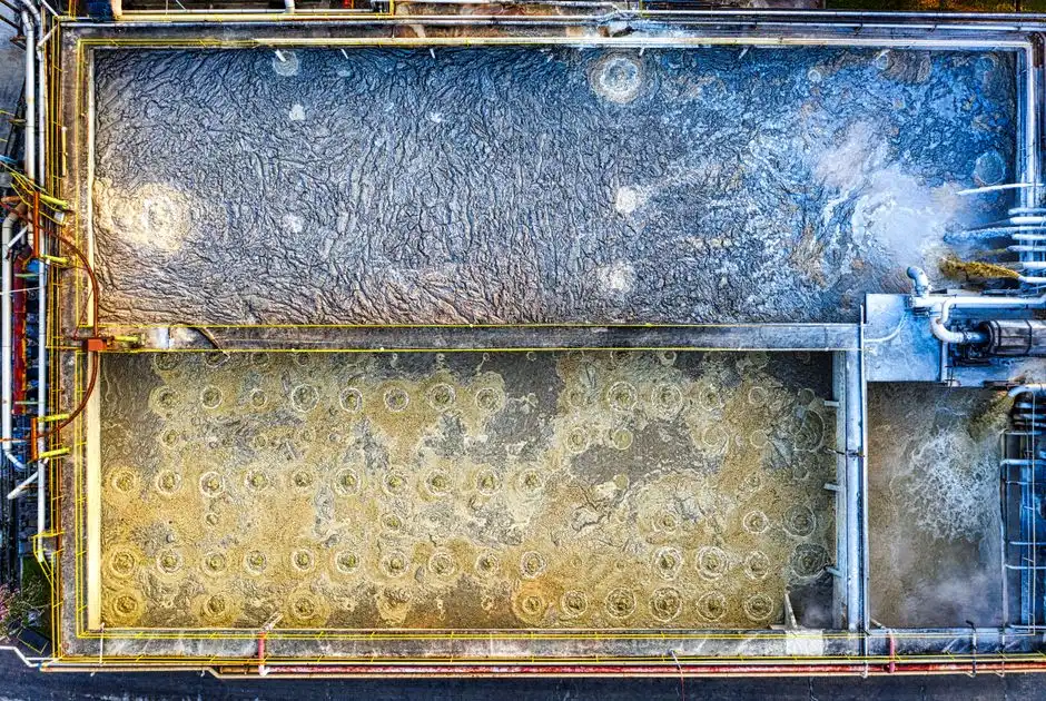
Size the DAF to peak hourly flow, not average. The dissolved air flotation system covers 4–300 m³/h across 13 models, so most plants fit a single skid; a plant with two distinct batch streams (e.g., a parts wash and a plating rinse) sometimes needs two smaller units in parallel for redundancy rather than one oversized unit. The chemical dosing skid should be sized for the maximum anticipated demand: coagulant pump at 50–200 mg/L × peak flow, flocculant at 1–10 mg/L × peak flow, and pH adjustment with enough acid/base capacity to correct a 4–11 excursion back to the 6.5–8.5 band within one equalization basin turnover. PLC control with automatic pH trim and flow-pacing is standard for 2026 specifications and reduces operator intervention to daily visual checks.
Sludge handling is the part most pretreatment specs leave undersized. The DAF float and any clarifier underflow must be dewatered before disposal, and a plate and frame filter press with 1–500 m² filtration area is the standard match for DAF solids yield — expect 3–8% dry solids in the DAF float and 25–35% dry solids in the filter cake. Footprint for a packaged train (screening + equalization basin + DAF + dosing + pH polish + multimedia filter) typically fits a 40–60 m² equipment room at a mid-sized plant, which is a useful constraint when retrofitting inside an existing manufacturing building near New Paris where floor space is at a premium.
2026 Compliance Checklist Before You Discharge to the Sewer
Before the next permit cycle, walk through this sequence with your POTW and EHS team. The steps below are the ones that most often get missed, and missing them tends to surface during an unannounced POTW inspection rather than during permit renewal.
- Confirm CIU status under 40 CFR Part 433 and/or Part 432 and obtain a control mechanism (the POTW-issued pretreatment permit) that names your categorical subpart, your sample locations, and your discharge limits.
- Submit a baseline monitoring report (BMR) for all categorical pollutants within 180 days of the categorical standard becoming applicable to your operation — this deadline is statutory and is not waivable by the POTW.
- Install and calibrate an effluent flow meter and a refrigerated composite sampler at the POTW connection; 24-hour composites are required for monthly-average compliance and daily grabs for the daily-maximum limit.
- Implement best management practices (BMPs) for chemical storage, spill prevention, and slug control; narrative local limits routinely require a written slug control plan that identifies maximum allowable discharge rates and triggers for batch dump.
- Document routine inspection, calibration, and training records in a format that can be produced during a POTW inspection; the absence of a calibration log is the single most common finding in 40 CFR Part 403 compliance audits.
The reason this checklist is worth running before you sign a purchase order for treatment equipment is that the categorical monitoring schedule and the slug control plan both feed back into the equalization basin sizing and the sampler location. A 24-hour composite sampler that pulls from a point downstream of the equalization basin but upstream of the DAF measures a different compliance envelope than a sampler at the POTW connection, and the wrong choice will cost you a re-permit cycle.
Frequently Asked Questions
Are all transportation equipment plants categorical industrial users?
A plant is a CIU if it discharges any process wastewater from a categorical operation to a POTW. For transportation equipment, that includes metal forming, machining, parts washing, plating, painting, and surface treatment — so most truck body, trailer, and heavy-equipment assembly plants near New Paris are CIUs under 40 CFR Part 433 and, if they run plating, Part 432 as well (per 40 CFR 403.3(j)).
What removal rates does a properly sized DAF achieve on oil and grease?
A correctly designed DAF with chemical emulsion breaking ahead of the float cell achieves 90–98% oil and grease removal on emulsified cutting fluid and parts-wash wastewater, typically dropping 1,000–2,000 mg/L influent to 10–50 mg/L in the clarified effluent at 15–30 minutes flotation-zone residence time.
What is the difference between PSES and PSNS, and when does each apply?
PSES applies to industrial sources that began construction before the publication of the proposed pretreatment standards for that industrial category; PSNS applies to sources that began construction after that date (per EPA categorical pretreatment standards page). New construction at a New Paris plant triggers PSNS, which is generally stricter than PSES.
How are local POTW limits calculated and approved?
Local limits are calculated using EPA's local limits development guidance, which covers maximum allowable loadings, pollutant of concern identification, data collection, and annual review; they must be developed and approved in accordance with 40 CFR 403.5(c) before EPA can enforce them as pretreatment standards at the end-of-pipe discharge (per EPA local limits page).
What happens during a POTW inspection, and what are the penalties for non-compliance?
A POTW inspection covers sample collection, records review (calibration logs, manifests, BMP documentation), and a walkthrough of chemical storage and process wastewater handling. Penalties for non-compliance escalate from a notice of violation to administrative orders, civil penalties up to $25,000 per day per violation under CWA Section 309, and possible permit suspension or revocation for repeat or willful violations.