
Why Plastics and Rubber Wastewater in Walkerton Stumps a Standard Clarifier
Plastics and rubber plants in the Walkerton, Indiana area generate a wastewater profile that a conventional gravity clarifier was never designed to handle. The stream carries latex residues from dip-molding and impregnation lines, plasticizer carryover (phthalates such as DEHP and DINP, plus adipate esters), mold-release oils and silicones, antistatic surfactants (typically quaternary ammonium or ethoxylated nonionics), hot-melt waxes from curing and trimming operations, polymer fines and rework pellets, and TDS spikes from acid and caustic wash cycles. Most of these contaminants have a specific gravity below 1.0 — oils, waxes, and re-emulsified plasticizers float rather than sink — while the surfactants and sub-100-micron polymer fines form stable colloidal suspensions that will not drop out under quiescent conditions, regardless of detention time.
Equalization tanks at these facilities often look like polymer-fouled swamps and clarifier skimmings come off as sticky, emulsified sludge instead of clean float. A DAF unit resolves this by saturating a pressurized side stream with air and releasing it into the flotation cell as a cloud of 30–50 micron microbubbles, which attach to chemically conditioned solids and carry them to the surface (Clearwater/SigmaDAF, 2026). For a small-to-medium Walkerton plant in the 50–500 GPM band discharging under Indiana NPDES general industrial permits to a local POTW, this mechanism — not gravity — is what does the work on a plastics or rubber stream.
How a Dissolved Air Flotation Unit Actually Works in a Plastics Plant
A DAF system operates on a recycle pressurization loop. A side stream — typically 20–50% of the influent flow — is saturated with air in a pressure vessel at 60–90 psig. When that recycle stream is released into the flotation cell at atmospheric pressure, the dissolved air comes out of solution and nucleates into the 30–50 micron microbubble cloud described in the SigmaDAF process literature (Clearwater/SigmaDAF, 2026). Those bubbles attach to chemically conditioned floc and lift it to the surface in a thick float blanket.
The chemistry upstream of the cell makes the separation work. A coagulant (typically a cationic polyaluminum chloride or ferric chloride) is dosed for charge neutralization, followed by a long-chain anionic or nonionic flocculant that builds a strong, low-density floe capable of catching bubbles. As the Spectrum Water technical note puts it directly, "a DAF with the wrong coagulant is an expensive tank" (Spectrum Water, 2026) — the unit is only as good as the jar-tested chemistry on the actual plant sample. Paddle skimmers then remove the float blanket, while heavier settleables drop to a collection zone and auger out the bottom. Two DAF architectures dominate: the high-profile FPBC-style design with a lamella pack for low-to-medium solids, and the high-flow FPHF design that combines cross-flow and countercurrent flow for higher hydraulic throughput.
Gravity Clarifiers in Plastics and Rubber Service: Where They Earn Their Keep
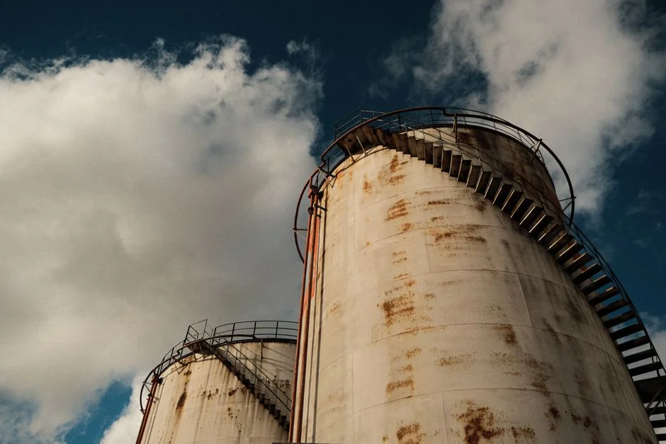
A conventional clarifier relies on long detention (2–4 hours) and a low surface overflow rate — typically around 1 m/h — to let settleable particles drop to a sludge blanket that a rotating rake scrapes toward a central hopper, while a surface scum skimmer removes the floating fraction (Illustrated Handbook of Water & Wastewater Treatment, 2017/2018). On an industrial wastewater stream, that geometry is effective only when the contaminant set is settleable: heavy grit, calcium carbonate from hard-water cooling, metal hydroxide precipitates from a prior precipitation step, or settled biological floc from an activated-sludge basin. It is largely ineffective on colloidal and floating fractions — which is exactly the fraction a plastics or rubber plant generates.
There are narrow use cases where a clarifier is the correct first step, such as a stream that is mostly settleable inorganics with negligible FOG, a low-FOG cooling-tower blowdown, or a lamella clarifier option deployed as a downstream polisher after a DAF and biological step. Lamella/inclined-plate designs raise the effective surface loading rate to roughly 20–40 m/h, but the separation principle remains gravity, and emulsified oil and stable polymer colloids do not drop out of a lamella pack any faster than they drop out of a round tank.
DAF vs Clarifier: Head-to-Head for Walkerton Plastics and Rubber Plants
The table below scores the two options on the parameters that drive a 2026 capital decision at a Walkerton-area plastics or rubber plant. Footprint numbers are anchored to documented mobile DAF packaging: the smaller WesTech mobile DAF trailer measures 47'-6" x 8'-6" and the larger unit 51'-7" x 8'-6" in operation, and the SigmaDAF COMPACT DAF is delivered as a single skid at flows of 66 GPM or less and a modular two-skid system above that (WesTech, 2026; Clearwater/SigmaDAF, 2026). No comparable mobile clarifier configuration is documented in the research record.
| Parameter | DAF (HydropureWater / FPBC / FPHF) | Gravity or Lamella Clarifier |
|---|---|---|
| Target contaminants on a plastics/rubber stream | Free and emulsified oil, plasticizers, latex, polymer fines, waxes, FOG, low-density TSS | Settleable inorganics, metal hydroxides, biological floc — not FOG or colloids |
| FOG removal performance | Documented workhorse; 80–95% FOG removal on properly conditioned streams | Minimal — emulsified oil passes through to downstream biology |
| TSS removal on a plastics stream | Typically 70–90% with jar-matched coagulant/flocculant | Variable; poor on colloidal polymer fines and floating fraction |
| Footprint per GPM | Compact; trailer/skid-mountable; small unit ~47'-6" x 8'-6" covers roughly 50–250 GPM | Large round or rectangular tank; typically 10–30x the footprint per GPM |
| Hydraulic detention | 15–30 minutes in the cell | 2–4 hours (conventional); 30–60 minutes (lamella) |
| Polymer demand | Higher — coagulant + flocculant both required; site-specific jar test mandatory | Lower when stream is genuinely settleable; often coagulant only |
| Sensitivity to flow surges | Moderate; recycle ratio smooths hydraulic swings; equalization still recommended | High; surges resuspend sludge blanket and short-circuit weir |
| Mobility / brownfield fit | Trailer or skid options documented at 50–1,000 GPM | No equivalent mobile configuration in the research record |
| 2026 capex framing | Higher unit cost; lower civil/site work; faster install | Lower unit cost; higher civil/site work; longer install |
| 2026 opex framing | Polymer chemistry is the dominant variable — request a site-specific jar test before sizing | Lower energy, lower polymer, but risk of NPDES surcharge from carryover FOG/TSS |
Spectrum Water's explicit positioning is that DAF is the right tool for material a clarifier struggles with — free and emulsified oil, grease, fiber, and low-density solids that do not fall out of suspension under gravity (Spectrum Water, 2026). The clarifier wins on energy and polymer cost only when the stream is genuinely settleable, which on a plastics or rubber line is the exception rather than the rule. The decision rule: if the stream contains oil, plasticizer, latex, or polymer fines, lead with DAF; if it is predominantly settleable inorganics, a clarifier (or lamella) is acceptable. Pair the DAF with an automatic chemical dosing skid sized to the jar-tested polymer demand so chemistry delivery does not become the bottleneck.
Sizing and Configuring the DAF for Your Walkerton Line
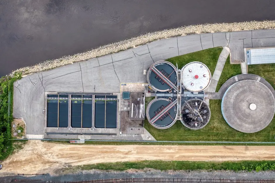
The DAF product family covers 13 standard models spanning 4–300 m³/h (roughly 18–1,320 GPM), with selection driven by peak flow, FOG/TSS load, and the required surface loading rate. For plants under 66 GPM, a single-skid turnkey architecture mirroring the SigmaDAF COMPACT packaging is the practical choice — the unit ships with chemical conditioning equipment, the flotation cell, sensors, instruments, and a PLC control panel, and is delivered plug-and-play for rapid commissioning (Clearwater/SigmaDAF, 2026). Above 66 GPM, plan on a modular two-skid layout or parallel units; the 50–1,000 GPM trailer/skid band is well-established in the mobile DAF market (Spectrum Water, 2026; WesTech, 2026).
Engineers should lock in two configuration items before the PO. First, a rotary bar screen for headworks ahead of the DAF to keep plastic pellets, trim scrap, and stringy release-film pieces out of the flotation cell, where they foul recycle pumps and plug nozzle packs. Second, an automatic chemical dosing skid with polymer make-down and jar-tested dose curves — manually tuned polymer feed is the most common reason a DAF underperforms its nameplate removal.
Decision Framework: Which Path for Your Walkerton Facility in 2026
Three paths cover the realistic 2026 scenarios at a Walkerton-area plastics or rubber plant.
Path A — DAF-first. FOG above 50 mg/L, visible oil or grease, plasticizer- or latex-bearing streams, flows in the 50–1,000 GPM band, and brownfield footprint constraints point to a DAF-led train. Pair the DAF with biological polishing (MBR or conventional activated sludge) to break down the dissolved organics the DAF does not touch, then dewater the floated sludge with a filter press for floated sludge to bring cake solids into a haulable range.
Path B — Clarifier-first (rare). Mostly settleable inorganics, negligible FOG, large available footprint, and very low polymer tolerance. This is realistic for a hard-water cooling-tower blowdown or a metal-finishing wash stream that happens to share a discharge point — not a typical plastics or rubber process line.
Path C — Hybrid. DAF for primary separation, then a lamella clarifier for secondary polish downstream of biological treatment. This is the most common configuration at larger Walkerton-area facilities and the one that satisfies the 2026 Indiana pretreatment expectation that each unit operation demonstrably protects the receiving POTW.
Frequently Asked Questions
What FOG and TSS removal can a Walkerton plant realistically expect from a DAF on a plastics stream?
On a properly jar-tested plastics or rubber stream, a DAF typically achieves 80–95% FOG removal and 70–90% TSS removal; lab jar tests on the actual plant sample are the only reliable way to confirm performance before sizing (per SigmaDAF and Spectrum Water process data, 2026).
How do I convert my Walkerton line flow from GPM to m³/h when sizing a DAF?
Multiply GPM by 0.227 to get m³/h; the DAF family covers 4–300 m³/h across 13 standard models, which spans roughly 18–1,320 GPM and brackets the typical small-to-medium plastics and rubber plant.
What is a realistic polymer-coagulant cost range I should budget for a DAF on a plastics or rubber stream?
Public plastics/rubber-specific benchmarks are not published, so budget against a site-specific jar test rather than a generic number — coagulant and flocculant demand on these streams is dominated by surfactant and plasticizer load, which varies sharply with product mix.