
Why Petroleum Wastewater Breaks the Simple Clarifier Assumption
Petroleum wastewater is a four-phase stream, and that single fact turns the DAF-vs-clarifier question from a default specification into a real engineering decision. The phases are: free oil (droplets above ~150 µm that rise rapidly under Stokes' law), emulsified oil (5–150 µm droplets stabilized by surfactants and shear), suspended solids (silts, catalyst fines, wax crystals, corrosion debris in the 1–100 µm range), and dissolved organics (phenols, BTEX, naphthenic acids). A refinery desalter, an oil-reclamation terminal, or a petroleum storage facility will see all four in the same equalized waste stream, often in the same hour, depending on which unit is draining.
The 1975 EPA Process Design Manual for Suspended Solids Removal (Chapter 7) laid out gravity settling, dissolved-air flotation, tube settlers, and wedge-wire straining as parallel process options for industrial service. That manual remains the most-cited design baseline for U.S. primary treatment, and it treats DAF as the dedicated option where floatables dominate (per EPA 625/1-75-003a, 1975-01).
Real oily-water performance proves the point. DAF Corporation's FC-150 Maximizer is rated for 500 GPM of raw wastewater at 2,000 PPM suspended solids, clarified down to 50 PPM — a 97.5% TSS reduction on a stream a gravity clarifier would return at 100–200 PPM. The takeaway for any Middletown, US plant engineer: gravity removes settleables; DAF removes floatables and fine suspended matter; petroleum streams contain both, so the decision is not which technology but which comes first.
How a DAF Clarifier Works on Oily Wastewater
A DAF clarifier operates via three working parts: a saturator, a recycle loop, and a flotation/separator tank. Roughly 20–40% of the clarified effluent is pulled off, pressurized with air at 60–80 psi in the saturator, and then recombined with the incoming oily stream at near-atmospheric pressure. The pressure drop releases the dissolved air as a cloud of 20–40 micron micro-bubbles (per DAF Corp's micro-bubble generator specification). These bubbles attach to oil droplets and fine suspended particles, lifting them to the surface as a float layer that is skimmed off, while heavier settleable solids drop to a bottom cone at 2–4% dry solids consistency (per DAF Corp).
Two geometries dominate the factory market. The FC Maximizer is a zero-velocity shallow circular tank, 6–70 ft in diameter, rated for 10–11,000 GPM at 92–98% TSS removal. The RC UniMax is a rectangular design, 10–1,000 GPM, at 85–90% TSS removal — a better fit for long, narrow site footprints or skid-mounting. For most Middletown refinery and terminal sites, the circular FC Maximizer is the default, with the RC UniMax reserved for retrofit or space-constrained skids. An industrial DAF system for petroleum wastewater sized to the FC-150 envelope (500 GPM, 2,000 PPM → 50 PPM) is a defensible reference point when specifying.
Chemical conditioning is the variable that separates a working DAF from a marginal one. WesTech's mobile DAF documentation specifies that while DAF can operate without coagulants, flocculant or coagulant dosing is recommended to improve float separation or sludge concentration (WesTech mobile DAF product page, accessed 2026). For variable refinery feeds, an emulsion-breaking polymer plus a coagulant is standard practice. A matched PLC-controlled coagulant and flocculant dosing system is the practical way to hold the dose ratio stable as flow and influent shift through the day.
How a Conventional Gravity Clarifier Works on the Same Stream
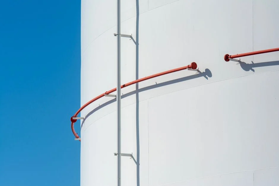
A primary clarifier — and by extension an API 421 separator used as one — is a quiescent tank that relies on Stokes-law settling. Oil droplets above ~150 µm rise to the surface; dense suspended solids above ~100 µm settle to the bottom. The 1975 EPA manual (Chapter 7, Section 7.5) sets the design envelope: typical overflow rates of 800–1,200 GPD/ft², hydraulic detention time of 1.5–2.5 hours, and expected TSS removal of 50–70% on raw municipal wastewater. On oily refinery influent, the same tank delivers 100–200 ppm effluent TSS and well under 60% removal of emulsified oil, because the 5–150 µm droplets neither rise nor fall fast enough inside the residence time window (per EPA 625/1-75-003a, 1975-01).
Refinery streams have physical advantages that get cited in vendor brochures but rarely move the needle in practice. Higher temperature lowers water viscosity and marginally improves oil-droplet rise velocity. A true API separator with corrugated plate packs performs better on free oil than a simple circular clarifier, which is why API 421 remains the upfront workhorse. However, the failure mode persists: emulsified hydrocarbons, surfactant-stabilized FOG, and sub-100 µm catalyst fines pass through the clarifier and land in the effluent. Without a downstream polish step, that effluent will not meet the 40 CFR Part 413 oil & grease envelope, and it will not satisfy a Middletown POTW local limit on sulfides or benzene.
DAF vs Clarifier: Head-to-Head Comparison for Petroleum Service
The following table provides a comparison for use in a 2026 capital-approval memo or pretreatment permit narrative. Numbers reflect DAF Corp published ratings (FC Maximizer and RC UniMax) and 1975 EPA design parameters updated with current field practice.
| Parameter | Dissolved Air Flotation (DAF) | Conventional Gravity Clarifier / API Separator |
|---|---|---|
| TSS removal efficiency | 92–98% (FC Maximizer, per DAF Corp) | 50–70% on raw wastewater; lower on oily streams (per EPA 1975) |
| FOG / emulsified oil removal | >95% free + emulsified with polymer | <60% on emulsified oil; >95% only on free oil in API separator |
| Typical effluent TSS | 20–50 ppm (DAF Corp FC-150 rating: 50 ppm) | 100–200 ppm on oily refinery influent |
| Hydraulic residence time | 20–40 minutes | 1.5–2.5 hours (per EPA 1975, Section 7.5) |
| Footprint per 100 GPM | ~0.5 m²/GPM (shallow tank, zero-velocity) | ~0.8 m²/GPM (deeper quiescent volume) |
| CAPEX band (skid, 100 GPM) | $$ (stainless, saturator, controls) | $ (concrete or coated carbon steel tank) |
| OPEX band | $$ (compressed air, polymer, skimmer drive) | $ (sludge pump, periodic desludge) |
| Feed variability tolerance | Recovers within minutes of an upset | Slow response; sludge blanket can wash out |
| Suitability for emulsified oil | Primary choice | Poor without upstream chemical break |
| Polymer consumption | 2–10 mg/L typical, jar-test dependent | None in basic operation; required if used as polish |
Two durability differentiators matter when the equipment is sited near a hydrocracker or a tank farm. DAF Corp's standard FC Maximizer is constructed of 304L stainless with epoxy-painted carbon-steel supports — fully stainless is optional — and is rated across the full 10–11,000 GPM range, with a one-year parts and labor warranty (per DAF Corp, 2026). The EPA 1975 manual classifies DAF as the dedicated option for streams where floatables dominate, and operating data since then supports this conclusion. If a site has a limited footprint or variable feed, the comparison tilts toward DAF; if it has a large open laydown area, low free oil, and high settleable-solids loading — for example, a desalter brine after oil has already been skimmed — a clarifier or an inclined-plate lamella clarifier for oil-removed streams is the appropriate primary unit.
2026 Compliance Context: 40 CFR Part 413 and Middletown Pretreatment
Petroleum refining is a categorical industry under 40 CFR Part 413, with oil and grease limits in the roughly 100 mg/L daily-max range and a priority-pollutant scan that includes lead, chromium, benzene, and phenols. The federal categorical standard is the floor; the ceiling is whatever the local POTW imposes through its pretreatment program. Middletown POTW pretreatment standards typically tighten TSS, sulfides, and benzene on top of the federal limits, and a refinery or terminal discharging without a polish step is exposed to a Notice of Violation if a slug reaches the headworks.
EPA's 2026 effluent guideline framework continues to tighten FOG and BTEX limits across refinery subcategories, and enforcement has shifted from end-of-pipe sampling to real-time monitoring at the categorical sampling point (per EPA effluent guidelines updates, 2026). Sizing a DAF with margin — such as the FC-150 envelope of 50 ppm TSS at 2,000 ppm loading — is an effective permit-renewal hedge. The same logic applies to oil-reclamation facilities, whose waste streams sit closer to the FOG ceiling than most refiners realize. DAF Corp's one-year labor and parts warranty provides the maintenance documentation a pretreatment coordinator expects during an audit, whereas a clarifier's sludge pump replacement history is rarely as well documented.
Selection Flowchart: When to Choose DAF, Clarifier, or Both
The following flowchart translates the comparison table into four if-then rules for application to influent data.
| Decision Rule | Influent Condition | Recommended Primary Unit | Why |
|---|---|---|---|
| 1. Free oil > 50 ppm OR emulsified oil present | Refinery desalter, tank-farm runoff, oil-reclamation decanter | DAF (FC Maximizer or RC UniMax) | Micro-bubble flotation captures what gravity cannot; 92–98% TSS, >95% FOG |
| 2. Free oil < 20 ppm and high settleable solids | Desalter brine after oil removal, coker blowdown post-DAF | Inclined-plate lamella clarifier | Small footprint, low OPEX, no air system; settleables drop, oil already gone |
| 3. Variable feed with oil slugs | Multi-source terminal, batch discharges | DAF primary + lamella polish | DAF absorbs the slug, lamella captures carryover solids before discharge |
| 4. Limited footprint (< 30 m² for 100 GPM) | Constrained refinery plot, skid-mount retrofit | DAF | ~0.5 m²/GPM vs ~0.8 m²/GPM for a clarifier at the same throughput |
The rule of thumb for a capital committee: For oily refinery wastewater, default to DAF; reach for a clarifier only after oil is already removed. This logic is further detailed in the Pickens, US petroleum wastewater selection guide and the 2026 pretreatment compliance guide for petroleum plants.
Frequently Asked Questions
DAF or clarifier for petroleum wastewater — which should a factory choose in 2026?
DAF is
Frequently Asked Questions
DAF or clarifier for petroleum wastewater — which is better?
The choice depends primarily on the density and particle size of the suspended solids. Dissolved Air Flotation (DAF) is generally superior for petroleum wastewater because oil droplets and emulsified hydrocarbons have a specific gravity lower than water, causing them to float rather than settle. DAF systems utilize micro-bubbles to accelerate this separation process, making them more efficient for light-phase contaminants.
Gravity clarifiers are more effective when the influent contains high concentrations of heavy, inorganic silt or dense metal hydroxides that naturally settle via gravity. In many Middletown refinery applications, a DAF is used as a primary treatment stage to recover free oil, while a clarifier may be used downstream for biological solids separation.
What TSS removal efficiency does a DAF system achieve on refinery wastewater?
A properly optimized DAF system typically achieves Total Suspended Solids (TSS) removal efficiencies ranging from 80% to 95%. When chemical coagulation and flocculation are applied upstream of the DAF, the removal of emulsified oil and grease often reaches 90% to 98%.
Performance is highly dependent on the hydraulic loading rate, which should generally be maintained between 1.0 and 2.5 gallons per minute per square foot (gpm/ft²) of surface area. Achieving the higher end of these efficiency ranges requires precise control of the air-to-solids ratio and consistent dosing of polymers.
How much does a DAF system cost per GPM for an oil refinery?
For industrial-grade DAF systems designed for refinery environments, capital costs typically range from $1,500 to $3,500 per gallon per minute (GPM) of treatment capacity. This price includes the flotation tank, saturation system, skimmer mechanisms, and integrated control panels, but excludes site-specific civil works or advanced tertiary filtration stages.
Operational costs, including power for air saturation pumps and chemical consumption for flocculants, typically add an ongoing expenditure of $0.05 to $0.15 per 1,000 gallons treated. Total project costs can vary significantly based on the metallurgy required to handle specific refinery wastewater corrosivity and local Middletown installation labor rates.
Does a DAF system meet 40 CFR Part 413 oil and grease limits?
Yes, a DAF system is a standard technology employed to help refineries achieve compliance with 40 CFR Part 413 (Electroplating Point Source Category) and similar effluent guidelines for oil and grease. When correctly sized, a DAF can reduce oil and grease concentrations from influent levels exceeding 500 mg/L down to discharge limits frequently required by local Middletown POTW permits, often below 50 mg/L or lower depending on the specific facility's discharge agreement.
To ensure consistent compliance, the system must be paired with an automated pH adjustment and chemical precipitation module. Without these pre-treatment steps, the DAF may fail to break stable emulsions, resulting in effluent oil and grease concentrations that exceed regulatory thresholds.
When is a gravity clarifier preferred over a DAF for refinery wastewater?
A gravity clarifier is preferred when the refinery influent is characterized by high concentrations of heavy, non-petroleum solids or when the process involves an activated sludge biological treatment stage. Clarifiers are the industry standard for secondary clarification to settle out biomass (sludge) where the biological floc is dense enough to settle naturally.
Additionally, gravity clarifiers are preferred when the wastewater lacks the oil content necessary to benefit from flotation, or when the operational budget cannot support the ongoing energy and chemical costs associated with a DAF saturation system. In scenarios with very high volumetric flow rates and low contaminant concentrations, the lower capital and maintenance costs of a simple circular clarifier provide a more favorable return on investment.