
How to Remove Chromium from Industrial Wastewater
To remove chromium from wastewater, reduce Cr(VI) to Cr(III) with ferrous sulfate or sodium metabisulfite at pH 2.0–2.5, then precipitate Cr(OH)3 at pH 8.0–9.0.
The regulatory floor is the WHO permissible limit of 0.05 mg/L total chromium in drinking water, restated by the 2025 Springer nanomaterial review (Verma et al, 2025) after aggregating global groundwater data. That review reports approximately 80% of wastewater returns to nature without adequate treatment, while roughly 66% of sampled groundwater exceeded the WHO limit. Men (66%), women (46%), and children (43%) all sat above a total hazard index of 1 in the aggregated hazard assessment. A non-compliant effluent at 0.5 mg/L total chromium is therefore 10× the WHO limit and typically 5× the industrial discharge cap of 0.1 mg/L.
Speciation drives the process choice because Cr(VI), present as chromate (CrO42−) or dichromate (Cr2O72−), is a confirmed carcinogen that stays mobile and soluble across pH 1–14. Cr(III) is far less toxic and hydrolyses to insoluble hydroxide above pH ~5, so the train converts the soluble species into a precipitable form. The 2025 Verma review characterised an electroplating wastewater at 302.80 mg/L total chromium and pH 2 — a feed no polishing step alone can handle. That pH is also low enough that the stream must pass through both reduction and precipitation before reuse or discharge.
Chromium Speciation and the Chemistry Behind Removal
Two chromium species dominate industrial wastewater: hexavalent Cr(VI) as chromate (CrO42−) or dichromate (Cr2O72−) depending on pH and concentration, and trivalent Cr(III), which hydrolyses to insoluble Cr(OH)3 above pH ~5. Cr(VI) is fully soluble across the entire pH range, so precipitation alone cannot strip it. You must first add electrons to reduce the metal, then raise pH to crash the reduced form out of solution.
The standard reduction half-reaction is:
Cr2O72− + 14 H+ + 6 e− → 2 Cr3+ + 7 H2O E° = +1.33 V
Industrial practice delivers those electrons with ferrous sulfate heptahydrate (FeSO4·7H2O), sodium metabisulfite (Na2S2O5), or sulfur dioxide gas — all cheap, water-soluble, and proven at full scale. FeSO4 is preferred when simultaneous precipitation of co-formed Fe(III) is acceptable, while Na2S2O5 is preferred when lower sludge volume matters. Most plants we size for electroplating rinse water run FeSO4 at the lower end of the stoichiometric range when sludge contracts are expensive.
For in-situ remediation of saturated soils and groundwater, calcium polysulfide (CaS5) and nanoscale zero-valent iron (nZVI) are documented as effective reductants in the 2020 Elahi review. That review also confirms biological Cr(VI) reduction is enzymatically driven by membrane-associated chromate reductases. Isolates such as Bacillus megaterium transfer the same electrons that FeSO4 does, only slower and at ambient temperature.
Once Cr(VI) is reduced, Cr(III) behaves as a typical transition metal: soluble at pH < 5, precipitating as amorphous Cr(OH)3 between pH 7 and 10, and redissolving above pH ~9.5 as amphoteric chromite complexes (Cr(OH)4−). That narrow precipitation window is why every stage of the conventional train is pH-locked.
The Standard Four-Stage Treatment Process
A buildable conventional chromium removal train has four sequential stages: equalisation and pH adjustment, reduction, precipitation, and polishing. The table below gives the operating envelope for each stage, and the text that follows explains the chemistry and equipment selections that hold those setpoints. Conventional trains target total chromium below 0.1 mg/L for industrial discharge.
| Stage | Target parameter | Operating range | Control signal | Residence time |
|---|---|---|---|---|
| 1. Equalisation / acidification | pH | 2.0 – 2.5 | pH probe | 2 – 4 h (buffer tank) |
| 2. Reduction (FeSO4·7H2O) | ORP | +200 to +300 mV | ORP probe | 20 – 40 min |
| 2. Reduction (Na2S2O5) | ORP | +200 to +300 mV | ORP probe | 20 – 40 min |
| 3. Precipitation | pH | 8.0 – 9.0 | pH probe | 30 min flocculation + 2 h settling |
| 4. Polishing | Total Cr | < 0.1 mg/L (or < 0.05 mg/L for reuse) | Online Cr(VI) analyser | 10 – 20 min contact |
Stage 1 — Equalisation and acidification. Flow and concentration surges from rinse tanks are smoothed in an equalisation basin, then sulfuric acid is dosed to drive pH to 2.0–2.5. This pH window maximises the reduction kinetics of both FeSO4 and Na2S2O5. It also keeps chromium in the dichromate form, which reacts faster than chromate under plant conditions.
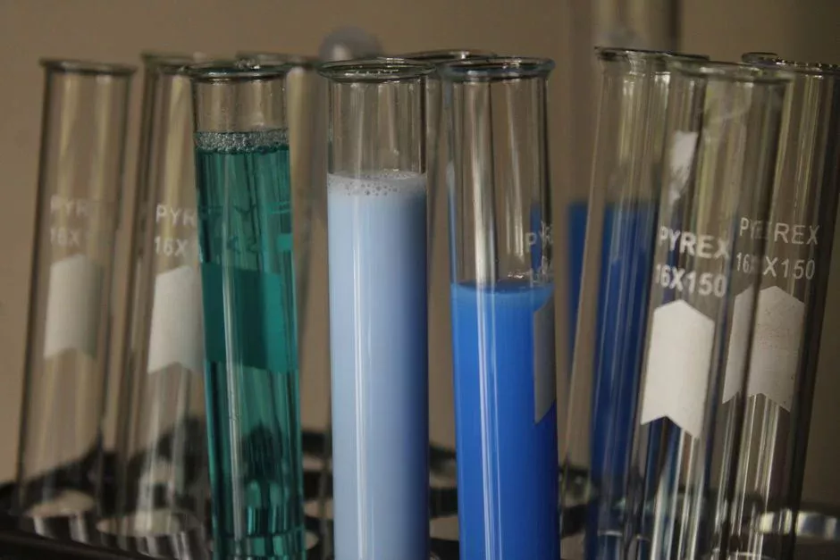
Stage 2 — Reduction. Dose FeSO4·7H2O at 2.5–3.0× the stoichiometric Cr(VI) requirement, or Na2S2O5 at ~1.8× stoichiometry, into a 20–40 min reaction tank with a PLC-controlled FeSO4 and NaOH dosing skid and an ORP probe. Target ORP is +200 to +300 mV versus Ag/AgCl, and a yellow-orange to pale green-blue color shift confirms Cr(VI) → Cr(III) conversion. Under-dosing leaves residual Cr(VI) that breaks through the clarifier, while over-dosing by 50% or more produces iron-rich sludge that doubles disposal volume.
Stage 3 — Precipitation. Raise pH to 8.0–9.0 with NaOH or lime so Cr(III) precipitates as Cr(OH)3. Settle the solids in a lamella clarifier for Cr(III) precipitation operated at 1–2 m/h overflow rate. Expected sludge yield is 3–6 kg dry solids per kg of chromium removed, dominated by co-precipitated Fe(OH)3 when FeSO4 is the reductant.
Stage 4 — Polishing. Clarified supernatant passes through a multi-media filter, then through either a strong-base anion exchanger or a reverse-osmosis unit. Use the anion exchanger when residual Cr(VI) must drop below 0.05 mg/L, and select RO when water reuse requires both TDS and chromium to fall. Strong-base anion resin regenerates with NaCl brine every 8–24 h depending on load, while RO suits ZLD or closed rinse loops.
Comparing Removal Technologies: Precipitation, Ion Exchange, Adsorption, and Membrane
Chemical precipitation is the conventional baseline when plants must remove chromium at 50–500 mg/L inlet. The table below compares the four technology families a process engineer will choose for primary or polishing duty, using the 2025 Verma nanomaterial review and standard industrial vendor data as the anchor.
| Technology | Target Cr species | Typical effluent (mg/L) | CAPEX band | OPEX driver | Best use case | Key limitation |
|---|---|---|---|---|---|---|
| Chemical precipitation (FeSO4 + NaOH/lime) | Cr(VI) → Cr(III) | 0.5 – 2.0 (pre-polish) | Low | Sludge disposal (3–6 kg DS/kg Cr) | Primary stage at 50–500 mg/L inlet | Cannot meet < 0.1 mg/L alone |
| Ion exchange (SBA anion for Cr(VI); cation for Cr(III)) | Both | 0.01 – 0.05 | Medium–High | Resin regeneration (brine + waste brine) | Polishing to discharge or reuse limit | Resin fouling by Fe, hardness |
| Adsorption (activated carbon, biosorbents, Fe3O4/CTAB, chitosan-coated iron oxide) | Mostly Cr(VI) | 0.05 – 0.5 | Medium | Adsorbent replacement (0.5–6.0 g/L dose) | Low-flow polishing, mine drainage | 12–24 h contact time at scale |
| Reverse osmosis / nanofiltration | Both | < 0.05 (permeate); 10–50× feed (concentrate) | High | Energy + concentrate disposal | Water reuse, ZLD trains | Concentrate management |
For electroplating, tannery, and battery-materials plants with inlet chromium in the 50–500 mg/L range, precipitation is almost always the first stage because no other technology handles that load at acceptable CAPEX. Polishing is where the choice matters: ion exchange is the workhorse for discharge-only duty, while a RO system for chromium polishing and water reuse fits closed-loop rinsing. The 2025 Verma review reports 89.6–100% Cr(VI) recovery with chitosan-coated iron oxide nanoparticles and 94.64% Cr(VI) removal with Fe3O4/CTAB at pH 4. Contact times of 12–24 h and dosages of 0.5–6.0 g/L still confine those adsorbents to low-flow polishing or brine treatment, not a 50 m³/h electroplating rinse line.
For the membrane side of the polishing train, the RO design criteria for the polishing step spec sheet is a useful companion. Engineers evaluating the sulfide precipitation variant of the chromium train should also weigh it against the FeSO4 baseline for high-Cr feeds.
Sludge Handling, Recovery, and Zero Liquid Discharge Options
Sludge, not reagent cost, determines whether a chromium removal design is viable on the plant floor. The conventional FeSO4 train yields 3–6 kg dry solids per kg Cr removed, which equals 30–60 m³ of thickened sludge per 1,000 m³ treated at 100 mg/L inlet. That volume is what drives the disposal contract and often the OPEX ranking.
Thickening to 70–80% moisture is followed by mechanical dewatering with a filter press for chromium hydroxide sludge or a screw press, producing a 25–35% dry-solids cake suitable for transport. In the EU, chromium-bearing precipitates from surface treatment fall under Waste Framework Directive 2008/98/EC as hazardous waste; in the US, electroplating sludges are listed as RCRA K061. A Wettz test or TCLP leach on the cake remains the standard regulator check, and the sludge dewatering design criteria for the Cr(OH)3 cake article covers polymer selection and cake-handling.
Recovery is the alternative to disposal when inlet chromium is high enough to pay for the extra containment. Sulfide precipitation with Na2S or NaHS at pH 7–9 produces a denser, lower-volume chromium sulfide sludge that downstream smelters accept as feed, at the cost of sealed reactors and gas-phase H2S scrubbing. Reverse-osmosis concentrate from any ZLD polishing train is itself a recovery stream: at 10–50× feed concentration it can feed a small electrowinning or precipitation skid and close the metal loop.
Where the chromium-treated stream still carries biodegradable organics from rinse or sanitary drains, finish COD and ammonia in a compact biological stage after metals are already below consent. An Underground Package Sewage Treatment Plant (WSZ Series) fits that polishing role without mixing hazardous Cr sludge into the biomass. Keeping residual Cr(VI) out of the package plant avoids shocking the microbial community.
Design Parameters, Common Failures, and the 2026 Compliance Checklist
The conventional train is reliable but unforgiving when setpoints drift outside the envelope below. Hold these operating bands as the design basis, not as textbook ideals that can be loosened on day one.
- Reduction tank: pH 2.0–2.5, ORP +200 to +300 mV (Ag/AgCl), residence time 20–40 min, FeSO4·7H2O dose 2.5–3.0× stoichiometry, Na2S2O5 ~1.8× stoichiometry.
- Precipitation tank: pH 8.0–9.0, 30 min flocculation with anionic polyacrylamide at 1–3 mg/L.
- Lamella clarifier: surface overflow 1–2 m/h, sludge bed 0.8–1.2 m, underflow 3–6% dry solids.
- Polishing: multi-media filter at 5–10 m/h, ion exchange at 10–15 BV/h, RO at 15–25 L/m²·h flux.
Three failure modes account for most compliance excursions on chromium lines. Residual Cr(VI) breaks through when ORP is not monitored, and a 50 mV drift high in the reduction tank can leave 5–10% of the Cr(VI) unreacted. Over-dosing FeSO4 at 4× stoichiometry or more doubles sludge mass and rarely improves effluent below 0.5 mg/L. pH excursions above 9.5 in precipitation redissolve Cr(III) as chromite complexes and push total chromium back into the supernatant, which a closed-loop PLC-controlled FeSO4 and NaOH dosing skid is meant to prevent.
Set analytical frequency early on every chromium line. Run a daily 1,5-diphenylcarbazide colorimetric test for Cr(VI) at the clarifier outlet and weekly ICP-OES for total chromium on the polished effluent. Keep continuous online ORP and pH on the reduction and precipitation stages. Before startup, work the seven-item checklist below against the actual consent and licensed disposal route.
- Confirm the jurisdiction-specific limit — US EPA 0.1 mg/L Cr(VI) for electroplating under 40 CFR 413; EU under Directive 2010/75/EU and the BAT-AEL for surface treatment.
- Verify the sludge is classified as hazardous and the disposal route is licensed.
- Commission with a third-party jar test on the actual feed to lock in dose rates.
- Verify the polishing resin or membrane is sized for the actual breakthrough curve, not the catalogue number.
- Lock ORP and pH alarms before first production rinse.
- Confirm cake TCLP or equivalent leach results meet the licensed disposal facility acceptance criteria.
- Document the regeneration or concentrate disposal path for the polishing step.
Who This Is For and Next Step
Plant engineers, EPC contractors, and procurement managers use this process guide when sizing chromium pretreatment for electroplating, tannery, or battery-materials wastewater. Teams chasing only sanitary COD without hexavalent chromium should look elsewhere, because the reduction–precipitation chemistry is unnecessary for those streams.
If you already have inlet chromium, pH, and discharge consent data, send those numbers for a dose and clarifier check. Use our chromium removal design inquiry to confirm polishing selection against your actual feed.
Frequently Asked Questions
What chemical reduces hexavalent chromium in wastewater?
Ferrous sulfate (FeSO4·7H2O) dosed at 2.5–3.0× the stoichiometric Cr(VI) requirement, or sodium metabisulfite (Na2S2O5) at ~1.8× stoichiometry, both at pH 2.0–2.5, reduces Cr(VI) to Cr(III). Subsequent pH elevation to 8.0–9.0 with NaOH or lime precipitates Cr(III) as Cr(OH)3. Sulfur dioxide gas is used in larger plants for the same reduction step at comparable stoichiometry.
What pH is needed to precipitate chromium hydroxide?
pH 8.0–9.0 is the standard Cr(III) hydroxide precipitation window used on industrial lines. Below pH 5, chromium stays in solution, and above pH 9.5 amphoteric chromite complexes such as Cr(OH)4− redissolve so total chromium rises in the supernatant. Hold pH in the 8.0–9.0 band with closed-loop control on the precipitation tank.
How much does industrial chromium treatment cost per cubic meter?
Operating cost is dominated by FeSO4·7H2O (USD 0.30–0.60 per kg, 2026 spot) and chromium-bearing sludge disposal on most electroplating lines. A conventional FeSO4 + NaOH train treating 100–300 mg/L inlet typically runs USD 1.5–4.0 per m³ of treated wastewater. That figure excludes sludge disposal, which can add USD 0.5–2.0 per m³ depending on hazardous-waste classification and haul distance.
Can chromium sludge be recovered for metal reuse?
Yes — sulfide precipitation at pH 7–9 with Na2S or NaHS produces a chromium-rich, low-volume cake that downstream smelters accept as feed. RO concentrate at 10–50× feed chromium is a second recovery stream and the natural by-product of any water-reuse polishing train. Both options become economically attractive when inlet Cr exceeds 500 mg/L and disposal fees are high.
Is biological Cr(VI) reduction used at industrial scale?
Biological reduction using Bacillus, Pseudomonas, Microbacterium, and fungal strains is documented in the 2020 Elahi review, where membrane-associated Cr(VI) reductase enzymes deliver the same electron transfer that FeSO4 does. Industrial-scale biological trains are not yet standard on plating lines. Ion exchange and reverse osmosis remain the chemical-free polishing options after a conventional reduction stage.