What a Disc Filter Process Flow Diagram Shows
A disc filter process flow diagram is a four-stream schematic: influent into the disc stack, filtrate from the outer housing, backwash supply from the filtrate launder, and backwash reject to sludge handling. Credible PFDs also mark upstream clarification or DAF, downstream UV or RO, and the ΔP or level loop that starts backwash.
Without those four streams and the setpoint logic, the drawing is only an illustration. The hardware is a vertical stack of grooved plastic discs clad in polyester or stainless mesh (10–60 µm aperture) on a hollow shaft inside a gravity or pressurized tank. Influent enters the stack center and is forced outward through the mesh; solids form a cake that improves capture as it builds.
On a HUBER RoDisc — the geometry most municipal engineers transcribe first — up to 65% of disc area sits below the waterline. A fixed overflow weir sets the upstream level that drives backwash control. The canonical train is primary sedimentation → activated sludge → secondary clarifier → disc filter → UV or RO. Keep fibrous debris off the mesh with a 3 mm rotary bar screen upstream of the disc filter.
Stream-by-Stream Walkthrough: Influent to Filtrate
Secondary clarifier overflow enters the disc filter through a flow-distribution weir into the inlet drum. On HUBER RoDisc designs, that fixed overflow weir holds a stable upstream water level — the controller watches this level because it rises with mesh head loss as cake thickens. From the inlet drum, water moves into the disc-stack center and is forced outward through the mesh under differential head.
Per the MDPI 2019 Billund WWTP study, an 18 µm mesh captured 89.7% of particles and cut influent SS from 20 mg/L to 3–8 mg/L. Cake-mediated capture beyond the bare mesh rating contributed to the 75.6% mass removal. Filtrate collects in the outer housing and discharges by gravity over the outlet weir to the next unit. Downstream SS targets are <10 mg/L for UV transmittance and SDI₁₅ <3–5 for RO feedwater.
Most plants we size for tertiary reuse run the lower end of that SDI window when biology is stable. The instrumentation block on the PFD carries four canonical tags for this stream group. FIT-301 is the influent flow transmitter, usually a magnetic meter on the inlet launder. LIT-301 is the level transmitter in the inlet drum — the primary backwash initiator on a gravity unit, because water level proxies ΔP.
PDI-301 is the differential pressure transmitter across the disc stack, redundant with LIT-301 for the 30–50 kPa setpoint logic. FIT-302 is the filtrate flow transmitter on the outlet launder, used to back-calculate recovery.
| Tag | Service | Location on PFD | Typical Range / Setpoint |
|---|---|---|---|
| FIT-301 | Influent flow | Inlet launder to drum | Full scale at design flow (e.g. 0–800 m³/h) |
| LIT-301 | Upstream water level | Inlet drum | ΔP equivalent 30–50 kPa triggers backwash |
| PDI-301 | Differential pressure | Across disc stack | 30–50 kPa setpoint, tertiary duty |
| FIT-302 | Filtrate flow | Outlet weir to next stage | 95–98% of FIT-301 at steady state |
The Backwash Loop and Reject-Handling Branch
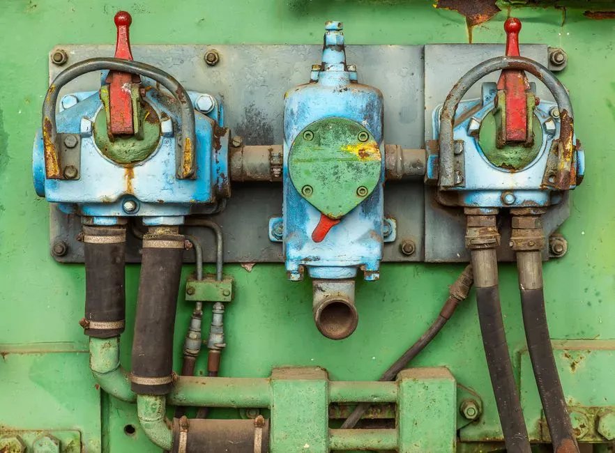
The backwash loop draws from the filtrate launder, not from raw water. When LIT-301 reaches the level matching a ΔP of 30–50 kPa (HUBER product documentation), the controller starts disc rotation and opens the spray bar — filtration does not stop. A backwash pump sized for spray-bar flow at 3–5 bar nozzle pressure pulls filtrate from the outlet launder and fires it through particulate-resistant nozzles at the mesh from outside. Dislodged cake plus spray water falls into an internal trough and discharges axially from the machine.
On continuous-rotation designs, only 5–15% of disc area is offline at any moment, and the cleaning window lasts 30–120 s before that segment returns to service. Upstream flow therefore sees no interruption; annotate the PFD as a partial-capacity event, not a shutdown line. Cake plus spray water can go to a sludge dewatering device — a filter press for the backwash reject stream is common when upstream biology already stabilizes solids — or return to head-of-works for re-treatment.
Quantify reject as 2–5% of disc-filter throughput, equivalent to 0.5–3% of total plant flow per commercial references. At 800 m³/h design flow, 2% reject is 16 m³/h (384 m³/day); 5% reject is 40 m³/h (960 m³/day). If the feed carries oil or grease, expect the upper end of this range and route reject through a dedicated handling train rather than back to headworks, where recycle would compound the FOG load.
Sizing the Disc Filter on the Flow Diagram
General hydraulic loading formula: design flow ÷ (number of discs × disc area × submergence factor). On a HUBER RoDisc, submergence is fixed at up to 65%, so the equation collapses to a disc-count calculation against effective area per disc. Worked example anchored to the MDPI 2019 Hydrotech HF2220 reference: 1200 m³/h across 13 discs at 18 µm and 65% submergence.
For an 800 m³/h design at the same 18 µm aperture, scale linearly: 800/1200 × 13 = 8.7, rounded up to 9 discs.
A HUBER RoDisc shaft carries up to 35 discs, so 9 discs fits inside a single-shaft envelope and leaves headroom for future capacity without a parallel train. OEM confirmation is mandatory before procurement. Disc diameter, spacing, and submergence fraction vary between HUBER and other platforms, and a 9-disc count on one geometry may deliver a different effective area than 9 discs on another.
For flows that exceed a single shaft's disc capacity, specify parallel trains rather than oversized shafts — maintenance access and redundancy both favor modular units. Reject volume is the second sizing output the PFD must show: at 95–98% recovery, expect 2–5% of throughput as reject. The sizing table below captures the numbers an engineer pencils onto the diagram.
| Parameter | Value | Source / Note |
|---|---|---|
| Reference unit | Hydrotech HF2220, 13 discs, 18 µm, 65% submergence | MDPI 2019 Billund study |
| Reference throughput | 1200 m³/h | MDPI 2019 Billund study |
| Design flow (worked example) | 800 m³/h | Engineer's design point |
| Calculated disc count | 800/1200 × 13 = 8.7 → 9 discs | Linear scale, OEM confirmation required |
| Single-shaft capacity (HUBER RoDisc) | Up to 35 discs | Manufacturer documentation |
| Recovery | 95–98% | Tertiary polishing duty |
| Reject rate | 2–5% of throughput (16–40 m³/h at 800 m³/h) | 0.5–3% of total plant flow |
Three Disc Filter PFD Variants: Reuse, Pre-RO, and Industrial
Variant A — municipal reuse / microplastic capture. Secondary clarifier → 18 µm disc filter → UV. This is the Billund reference train: 89.7% particle count removal, 3–8 mg/L effluent SS, and 95–98% recovery. The dominant failure mode is rapid blinding when 10 µm mesh is specified without an effluent-SS justification; stay at 15–18 µm unless downstream limits demand finer.
Compact sites sometimes package secondary biology and tertiary polishing inside an Underground Package Sewage Treatment Plant (WSZ Series) before the disc-filter boundary.
Variant B — pre-RO polishing. Secondary clarifier (or DAF) → 40–60 µm disc filter → cartridge filter → RO. The coarser mesh extends backwash intervals and reduces reject volume, which is why it dominates seawater and brackish RO pretreatment trains. The dominant failure mode is SDI creep when upstream biology is unstable; specify a redundant LIT/PDI on the disc filter outlet and alarm at SDI₁₅ > 5.
Variant C — industrial with FOG/TSS. DAF upstream for oil/grease removal → 3 mm bar screen → disc filter (typically 18 µm) → RO or reuse. HUBER specifies zero oil/grease to the disc filter, so a DAF pre-treatment for FOG and TSS reduction ahead of the disc filter is non-optional on this duty.
The dominant failure mode is FOG breakthrough when the DAF is undersized. Verify the DAF's oil removal guarantee on the same flow and temperature envelope. Protect the downstream RO membrane protected by the disc filter with an SDI₁₅ interlock before the high-pressure pump starts.
| Variant | Pre-treatment | Mesh | Next Stage | Dominant Failure Mode |
|---|---|---|---|---|
| A — Reuse / microplastic | Secondary clarifier | 18 µm | UV disinfection | Rapid blinding at 10 µm |
| B — Pre-RO polishing | Secondary clarifier or DAF | 40–60 µm | Cartridge + RO | SDI creep from unstable upstream biology |
| C — Industrial FOG/TSS | DAF + 3 mm bar screen | 18 µm | RO or reuse | FOG breakthrough if DAF undersized |
Engineers can insert an AOP skid between the disc filter and final disinfection for advanced oxidation. For refractory COD or metals, review a separate electrocoagulation flow diagram as an alternative upstream of the disc filter. For a downstream AOP train, the matching AOP process flow diagram for advanced polishing after the disc filter covers boundary tags and the oxidant dosing loop.
How Does an Activated Sludge Process Diagram Connect?
An activated sludge process diagram places the disc filter after the secondary clarifier, not inside the aeration basin. Clarifier overflow is the disc-filter influent; return and waste activated sludge stay on their own loops. An MBBR still needs a clarifier or sieve before a disc filter. An MBR process flow diagram replaces secondary clarification and fine filtration with the membrane tank, so a disc filter is usually omitted downstream.
Automobile plant water treatment flow often adds DAF for paint and FOG waste before biology, then uses the same clarifier → disc filter → RO sequence when rinse water is reused. Keep the four disc-filter streams on a separate sheet or dashed boundary so the biology PFD stays readable.
How Does a Closed-Loop Filter System Diagram Differ?
A closed-loop filter system diagram recirculates filtrate or reject inside a defined duty envelope, whereas a municipal disc-filter PFD is usually once-through tertiary polishing. Closed-loop sketches still need the same four streams, but reject often returns to an equalization or DAF node instead of plant headworks. On industrial reuse loops, annotate recovery (95–98% on tertiary duty) and the FOG interlock so operators do not recycle oil onto the mesh.
Selection checklist before you freeze the PFD. Match mesh aperture to duty: 15–18 µm for reuse, 40–60 µm for pre-RO. Set LIT/PDI backwash at 30–50 kPa equivalent. Route reject at 2–5% of throughput, and keep an upstream screen ≤3 mm with DAF if FOG is present.
Also confirm an SDI₁₅ alarm before RO, a single-shaft disc count with OEM area confirmation, and a parallel train if flow exceeds one shaft. Compact industrial pads sometimes combine equalization and biology in an Underground Package Sewage Treatment Plant (WSZ Series) ahead of the disc-filter skid.
Who this is for: EPC and plant engineers drafting tertiary reuse, pre-RO, or FOG-bearing industrial PFDs who need tag lists, reject math, and mesh rules on one page. Who should look elsewhere: teams specifying MBR-only trains without a polishing disc filter, or pure chemical process sheets unrelated to solids polishing. Next step: send design flow, mesh target, and reject destination with your disc filter sizing inquiry so the duty envelope can be checked before procurement.
Frequently Asked Questions
What mesh aperture should be specified on a disc filter PFD for tertiary reuse?
15–18 µm is the standard for municipal tertiary reuse and microplastic capture; the MDPI 2019 Billund study used 18 µm and recorded 89.7% particle count removal, 75.6% mass removal, and 3–8 mg/L effluent SS. Specify 10 µm only when a downstream reuse limit or high-fouling RO feed genuinely requires it, because every halving of pore size roughly doubles backwash load.
What ΔP setpoint initiates the backwash cycle on a disc filter PFD?
30–50 kPa across the disc stack for tertiary polishing duty, per HUBER product documentation. On a gravity-flow RoDisc, the controller watches LIT-301 (upstream water level) because it rises in proportion to ΔP; a redundant PDI-301 across the stack provides the direct measurement and the alarm.
How much reject does a disc filter generate, and where should it be routed?
Reject accounts for 2–5% of disc-filter throughput (0.5–3% of total plant flow). At 800 m³/h design flow that equals 16–40 m³/h (384–960 m³/day). Route cake plus spray water to a filter press when solids are already stabilized, or return to head-of-works when FOG is low; with oil or grease present, use a dedicated reject train.
How many discs are needed for an 800 m³/h tertiary design?
Nine discs is the linear scale from the MDPI 2019 Hydrotech HF2220 reference of 1200 m³/h on 13 discs at 18 µm and 65% submergence (800/1200 × 13 = 8.7, round up). A HUBER RoDisc shaft holds up to 35 discs, so nine discs fits one shaft, but OEM area confirmation is still required before purchase.
Can a disc filter sit directly after DAF on industrial FOG duty?
Only after DAF plus a ≤3 mm bar screen, and only when oil and grease to the mesh are effectively zero per HUBER guidance. Undersized DAF is the dominant failure mode on Variant C trains; verify oil removal on the same flow and temperature envelope and interlock RO start on SDI₁₅.