
What Is Electrocoagulation and Why It Works
An electrocoagulation system works by passing direct or pulsed current through sacrificial metal electrodes immersed in wastewater, dissolving the anode to release metal ions (Al³⁺ or Fe²⁺) that hydrolyze into coagulant species in situ. These destabilize colloids, precipitate heavy metals and phosphates, and float flocs via cathodic hydrogen micro-bubbles — eliminating the external chemical dosing room entirely. The citable definition, from Lim et al. in Chemistry – An Asian Journal (2026-08), frames EC as "an electrochemical wastewater treatment technique that removes contaminants via in situ generation of metal (oxy)hydroxide coagulants from anode dissolution" (source: Lim et al., Chem. Asian J. 2026-08, DOI 10.1002/asia.70938).
Three mechanisms run simultaneously inside the cell. The anode dissolves to release coagulant precursor ions. The cathode reduces water to generate H₂ micro-bubbles that float the resulting floc to the surface, an inherent flotation step. Charged colloidal particles migrate electrophoretically toward the counter-electrode, accelerating destabilization. The coagulant dose is set by current × time through Faraday's law, not by a chemical pump calibration, and there is no PAC or PAM inventory to manage. Removal targets documented across municipal and industrial studies include heavy metals (As, Cr, Pb, Cd), phosphate, fluoride, suspended solids, emulsified oils and FOG, textile dyes, and turbidity (source: Kato & Kansha, Environ. Sci. Pollut. Res. 2024).
The Three Electrochemical Reactions Inside an EC Cell
Anode dissolution supplies the coagulant. The half-reaction is M → M^(n+) + ne⁻, where M is aluminum (n = 3) or iron (n = 2 for Fe²⁺ released, which then oxidizes to Fe³⁺ in aerated systems). The mass of metal released is governed by Faraday's law, M = (I·t·M_w)/(n·F), where I is current, t is time, M_w is molar mass, n is valence, and F is Faraday's constant (96,485 C/mol). For an aluminum anode at 100 A operating for 60 min, theoretical release is 6.69 g Al — which hydrolyzes into roughly 96 g of Al(OH)₃ floc, enough to treat 1 m³ of moderately loaded industrial wastewater at a design current density of 80–150 A/m² (source: Ingelsson et al., Water Res. 2020).
The cathode reduces water rather than depositing the metal. The half-reaction is 2H₂O + 2e⁻ → H₂↑ + 2OH⁻. The hydrogen micro-bubbles have diameters of 20–60 µm, which is small enough to attach to destabilized flocs and carry them upward. Bubble density scales linearly with current density up to roughly 200 A/m², above which coalescence degrades the flotation efficiency (source: Abdollahi et al., Chemosphere 2022).
In the bulk water, the released metal ions hydrolyze into polynuclear coagulant species. Aluminum forms Al₁₃ (the Keggin-structured Al₁₃O₄(OH)₂₄^(7+)) and amorphous Al(OH)₃; iron forms Fe(OH)₂, Fe(OH)₃, and polymeric Fe–O–OH phases. These species adsorb onto colloid surfaces, neutralize surface charge, and sweep suspended solids as they precipitate. Phosphate co-precipitates as AlPO₄ or as FePO₄·2H₂O (source: Lim et al., Chem. Asian J. 2026-08). The failure mode to flag: at high pH near the cathode, dissolved metal can re-precipitate as an oxide passivation layer on the anode, which is the dominant degradation mechanism that pulsed waveforms were developed to solve.
Electrode Materials, Pairings, and What to Specify
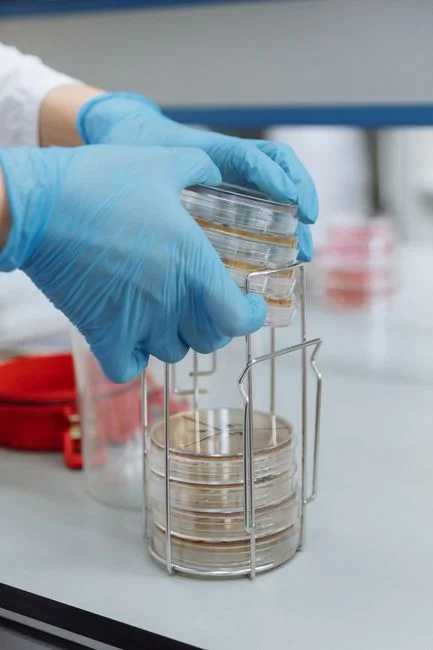
Aluminum anodes are the default for color, phosphate, fluoride, and potable-grade reuse applications because the Al(OH)₃ floc is low-density and easy to skim, and residual aluminum in effluent is generally below 2 mg/L when pH is controlled between 6.5 and 7.5. Iron anodes are preferred for arsenic, chromium, lead, and high-COD streams because Fe(OH)₃ produces denser, more magnetic sludge that dewaters to 22–28% DS in a plate-and-frame filter press, compared to 18–22% for Al(OH)₃ sludge (source: Bandaru et al., Water Res. 2020).
Stainless steel (SS-304 or SS-316) is normally the cathode because it is non-sacrificial. The Lim et al. 2026-08 study used SS-304 as both electrodes in its baseline tests, then swapped the cathode to Al-6061 to quantify the hybrid effect. The dissimilar SS(A)-Al(C) pairing hit 69.9% phosphate removal in 20 min versus 45.2% for SS(A)-SS(C), a 24.7-percentage-point gain attributed to galvanic interaction accelerating the sacrificial dissolution of the aluminum cathode during the off-pulse (source: Lim et al., Chem. Asian J. 2026-08).
Geometry matters at the PO stage. Plate electrodes in a parallel array are the most common and easiest to clean; concentric tube designs boost current density per unit footprint by 2–3× but complicate sludge removal; fluidized-bed sacrificial electrodes (typically aluminum or iron granules) maximize anode surface area but require an external recirculation pump and periodic media replacement. The trade-off is footprint versus maintenance access — plate arrays win on simplicity, fluidized beds win on high-strength streams above 5,000 mg/L COD or TSS.
| Electrode Material | Typical Role | Best-Fit Contaminants | Key Trade-off |
|---|---|---|---|
| Aluminum (Al-6061, Al-1050) | Sacrificial anode or cathode | Phosphate, fluoride, dyes, turbidity | Passivates in high-silica water; low-density sludge |
| Iron (Fe, low-carbon steel) | Sacrificial anode | Arsenic, Cr, Pb, high COD, FOG | Higher Fe residual in effluent if pH not controlled; magnetic sludge aids dewatering |
| SS-304 / SS-316 | Non-sacrificial cathode (occasionally anode in hybrid pairs) | Hybrid pairing to boost Al dissolution | Does not dissolve under normal polarity; SS-304 anode passivates within minutes under DC |
| Hybrid SS(A)-Al(C) | Both electrodes dissimilar | Phosphate, mixed streams | +24.7 pp phosphate removal in 20 min vs. SS-SS at same current |
DC vs. Pulsed Current vs. Pulsed Voltage: What 2026 Data Shows
Waveform selection is the single most consequential decision on the purchase order, and the 2026 data now makes the answer quantitative. Under direct current, the Lim et al. baseline delivered only 4.7% Faradaic efficiency, meaning more than 95% of the current was wasted on ohmic heating, water electrolysis, and anode passivation. Pulsed direct current improved Faradaic efficiency only marginally to 5.6%, because the off-pulse was too short for the aluminum oxide layer to depolarize (source: Lim et al., Chem. Asian J. 2026-08).
Pulsed direct voltage at 5 Hz, in contrast, achieved a Faradaic efficiency of more than 74.0%, with phosphate removals of 80.0% ± 1.3% at 20 min and 99.9% ± 0.1% at 120 min. The energy-specific removal rate reached 186.5–208.7 g PO₄³⁻/kWh at the 20-min mark, approximately threefold the DC/PDC baseline. Among 1 Hz, 5 Hz, and 10 Hz tested in the same work, 5 Hz delivered the best balance between enhanced anode dissolution during the on-pulse and capacitive recovery during the off-pulse (source: Lim et al., Chem. Asian J. 2026-08).
The mechanism is depassivation. Under DC or PDC, a thin insulating Al₂O₃ layer forms on the anode within minutes, choking further dissolution and forcing the cell voltage to climb. Under PDV at 5 Hz, the voltage collapses during the off-pulse, the oxide layer partially dissolves back into the bulk, and the next on-pulse strikes a cleaner surface. Abdollahi et al. documented this in their 2022 waveform review and confirmed it with a 2025 polarity-reversal study showing that periodic swapping of anode and cathode roles dissolves the passivation layer in situ and sustains Faradaic efficiency above 70% over hundreds of hours of operation (source: Abdollahi et al., Chemosphere 2022; Abdollahi et al., Environ. Res. 2025-05).
| Waveform | Faradaic Efficiency | Phosphate Removal (20 min) | Energy Efficiency (g PO₄³⁻/kWh) | Anode Passivation |
|---|---|---|---|---|
| Direct Current (DC) | 4.7% | ~25% (typical) | ~60 | Severe within minutes |
| Pulsed DC (PDC) | 5.6% | ~28% (typical) | ~70 | Moderate; off-pulse too short |
| Pulsed DV (PDV) 5 Hz | >74.0% | 80.0% ± 1.3% | 186.5–208.7 | Mitigated by off-pulse depolarization |
For engineers writing the spec, the practical takeaway is to request a programmable rectifier capable of constant-voltage mode with adjustable frequency (1–10 Hz) and duty cycle (30–70%), rather than a fixed-DC power supply. PDV delivers a roughly 3× energy-efficiency improvement, which is detailed further in the electrocoagulation system energy efficiency guide.
Operating Parameters That Drive EC Performance
Current density is the master variable. The 10–300 A/m² window covers most applications; below 10 A/m² coagulant generation is too slow, above 300 A/m² water heating and passivation dominate. The Lim et al. 5 Hz PDV work ran at intermediate current densities of 50–120 A/m², which is a reasonable starting point for a phosphate-removal application (source: Lim et al., Chem. Asian J. 2026-08). Electrode spacing of 5–20 mm is typical; tighter gaps reduce ohmic drop but increase short-circuit risk from sludge bridging, especially in high-TSS streams. Treatment time of 10–60 min is standard, and the 20-min and 120-min PDV data points are realistic design targets for phosphate polishing.
pH is the most commonly missed variable. The optimal band is 6–8, with the iron system tolerating a slightly wider window (5.5–9) than the aluminum system (6–7.5) because Fe(OH)₃ is less soluble at higher pH. Below pH 5, metal hydroxide stays in solution and removal efficiency collapses; above pH 9, the metal re-dissolves as aluminate or ferrate and the coagulant is lost. Conductivity below 1 mS/cm forces cell voltages above 30 V, which wastes energy and accelerates side reactions; dosing 0.5–2 g/L NaCl brings the cell into the practical operating range. Temperature between 20–40 °C improves kinetics; above 60 °C passivation accelerates and electrode lifetime drops.
| Parameter | Typical Range | Design Target for Phosphate | Failure Mode Outside Range |
|---|---|---|---|
| Current density (A/m²) | 10–300 | 50–120 (PDV 5 Hz) | <10: too slow; >300: passivation + heating |
| Electrode spacing (mm) | 5–20 | 10–15 | <5: short-circuit risk; >20: ohmic losses |
| Treatment time (min) | 10–60 | 20 (80% removal) / 120 (99.9%) | Diminishing returns past 60 min for most streams |
| pH | 6–8 | 6.5–7.5 (Al); 5.5–8.5 (Fe) | <5: metal stays soluble; >9: redissolution as aluminate/ferrate |
| Conductivity (mS/cm) | 1–5 | ≥1.5 (add NaCl if lower) | <1: cell voltage >30 V, energy wasted |
| Temperature (°C) | 20–40 | 25–35 | >60: passivation accelerates |
How Electrocoagulation Fits Into a Full Treatment Flowsheet
EC is a primary treatment step that replaces the chemical coagulation train. Upstream, a rotary mechanical bar screen and equalization basin remove rags, grit, and flow spikes that would otherwise foul or short the electrodes. The EC reactor itself can replace coagulant dosing, flash mixing, flocculation, and primary clarification in a single unit, cutting the coagulation-stage footprint by 40–60% in retrofit projects (HydropureWater field data, 2026).
Downstream, a dissolved air flotation (DAF) system or a lamella clarifier polishes residual suspended solids carried over from the EC tank. The EC reactor produces two sludge streams: a floating layer skimmed from the top and a settled bottom sludge; both are routed to a plate-and-frame filter press for dewatering to 22–28% DS before disposal. Where pH correction is required upstream of biological polishing or membrane treatment downstream, pair the EC skid with a PLC-controlled chemical dosing system sized for caustic or acid trim only, not coagulant.
Two failure cases define when NOT to specify EC. Streams with conductivity below 500 µS/cm require electrolyte addition that often costs more than the chemical savings justify. Streams with oil loading above 2,000 mg/L coat the electrodes and collapse Faradaic efficiency within hours; a CPI or DAF oil-removal stage must come first. For high-turbidity or dye-heavy streams, the high-turbidity wastewater treatment guide and the textile wastewater treatment guide walk through the integration sequence in more detail.
Limitations, Passivation, and How to Mitigate Them
Anode passivation is the dominant failure mode in aluminum and iron EC systems. A thin insulating oxide layer (Al₂O₃ or Fe₂O₃/FeOOH) forms on the anode within minutes under DC, blocking further dissolution and forcing the rectifier into a higher-voltage regime that mostly heats water. Lim et al. 2026-08 confirmed that 5 Hz pulsed direct voltage mitigates this by allowing the oxide layer to depolarize during each off-pulse, sustaining a Faradaic efficiency above 74% over multi-hour operation. Polarity reversal is a complementary strategy — Abdollahi et al. 2025-05 demonstrated that swapping anode and cathode roles on a 5–15 min cycle dissolves the passivation layer in situ and keeps removal efficiency stable beyond 200 operating hours (source: Abdollahi et al., Environ. Res. 2025-05).
Electrode wear is calculable. For an aluminum anode at 100 A/m² operating 12 h/day, theoretical consumption is 1.2–1.5 kg Al per square meter of anode per year; budget for full anode replacement every 6–24 months depending on current density, pH, and water matrix. Energy cost is the second-largest line item: even with PDV, EC consumes 0.5–3 kWh/m³, which is justified only on the basis of eliminated coagulant chemical costs and 30–50% lower sludge volume compared to chemical precipitation. The sludge itself is metal-rich and frequently classified as hazardous waste under local equivalents of EPA 40 CFR 261 — verify the disposal classification before commissioning, and budget for a filter press cake analysis in the commissioning report (source: Yasri et al., Water Sci. Technol. 2022).
Frequently Asked Questions
How does an electrocoagulation system work without adding chemicals?
The sacrificial anode dissolves under an applied current to release metal ions (Al³⁺ or Fe²⁺) directly into the wastewater. These ions hydrolyze in situ into metal (oxy)hydroxide coagulant species that destabilize colloids, precipitate phosphate and heavy metals, and float to the surface on cathodic hydrogen micro-bubbles. No external coagulant dosing pump, PAC, or PAM is required (source: Lim et al., Chem. Asian J. 2026-08).
Which contaminants can electrocoagulation remove?
EC is effective across a broad contaminant set: heavy metals (arsenic, chromium, lead, cadmium), phosphate, fluoride, suspended solids, emulsified oils and FOG, textile dyes, and turbidity. Removal rates of 80–99% are achievable in the right pH and current-density window, with iron electrodes preferred for metals and aluminum preferred for phosphate and color (source: Kato & Kansha, Environ. Sci. Pollut. Res. 2024).
Which electrode and waveform configuration gives the best performance in 2026?
The 2026 peer-reviewed benchmark is 5 Hz pulsed direct voltage paired with hybrid SS-304 anode / Al-6061 cathode electrodes, which delivers more than 74% Faradaic efficiency and 99.9% phosphate removal in 120 min — approximately threefold the conventional DC baseline. Specify a programmable constant-voltage rectifier with adjustable frequency and a hybrid electrode array on the PO (source: Lim et al., Chem. Asian J. 2026-08).
What is the energy consumption of an electrocoagulation system?
EC consumes 0.5–3 kWh/m³ depending on influent strength, target contaminant, and waveform. Pulsed direct voltage at 5 Hz cuts energy use by approximately 3× versus direct current by raising Faradaic efficiency from under 6% to over 74%, which means the same phosphate removal is achieved at a third of the kWh (source: Lim et al., Chem. Asian J. 2026-08; Abdollahi et al., Chemosphere 2022).
What unit operations should follow electrocoagulation in a treatment train?
Route EC effluent to a dissolved air flotation (DAF) unit or a lamella clarifier to polish residual suspended solids, then to biological or membrane treatment depending on the discharge target. The EC sludge — both the floating scum and the settled bottom fraction — is sent to a plate-and-frame filter press for dewatering to 22–28% DS before disposal, since the metal-rich cake is usually classified as hazardous waste.