
Why a Disciplined Commissioning Protocol Pays for Itself
A wet-out with the wrong water chemistry is the most expensive mistake a nanofiltration start-up can make. A single 8-inch NF element costs USD 600–1,200, a 4-vessel pressure vessel holds six elements, and a 12-month feed-specific warranty is void the moment incompatible chemistry touches the membrane. On a mid-sized municipal skid, one botched commissioning can write off USD 15,000–35,000 in wetted parts before the first cubic meter of permeate is sold — a number that dwarfs the 80–120 engineering hours required to write and execute a proper Inspection and Test Plan (ITP). The protocol that follows is built on the methodology of BS EN 15287 for engineered process equipment (BSI, 2026) and is structured in four sequential phases: pre-mount verification, mechanical installation, wet-out and CIP passivation, and a quantified performance acceptance test. The hand-over boundary is a signed acceptance certificate, which is granted only after the four-phase ITP has cleared every hold point.
Pre-Mount Verification and Site Readiness
Pre-mount verification begins long before the first wrench-strike. By the time the equipment arrives, every item below must have a documented pass entry to ensure installation day remains a mechanical work front rather than a problem-solving exercise.
- Foundation and skid leveling. Grout must cure a minimum of 72 hours before the skid is loaded, and the skid must be level to ≤2 mm/m on both axes. Anchor bolt torque values follow the equipment drawings — typically M16 at 190 N·m or M20 at 370 N·m for chemical-process skids, verified with a calibrated torque wrench.
- Piping stress and support spacing. Confirm expansion loop alignment and verify support spacing against the process piping code in force (typically MSS SP-69 / ASME B31.3 for chemical service). Pipe hanger spacing of 3 m for 2-inch and 4.5 m for 3-inch FRP/PP-R runs is a workable rule of thumb pending the isometrics.
- Instrument calibration. Conductivity, pH, ORP, pressure transmitters, and flow meters must carry calibration certificates traceable to NIST or equivalent national standards, with validity dates extending past the planned hand-over. A bench check against portable reference standards is required on day one — paper certificates alone are not sufficient.
- Electrical and utilities. Verify three-phase rotation on the high-pressure pump motor, grounding resistance ≤5 Ω, and instrument air pressure dew point ≤ -40°C to keep pneumatic actuators and control valves dry. CIP supply water must already be on site at TDS <50 mg/L before any NF element is loaded.
Chemical dosing for antiscalant and CIP injection is best commissioned in parallel with the skid; PLC-controlled automatic chemical dosing systems are normally lined up during this pre-mount window so that injection interlocks are live the moment process water flows.
| Pre-Commissioning Punch-List Item | Acceptance Criterion | Verification Method |
|---|---|---|
| Skid level | ≤ 2 mm/m on both axes | Digital level, two orthogonal readings |
| Anchor bolt torque | Per drawing (e.g. M16 = 190 N·m) | Calibrated torque wrench, 100% of bolts |
| Grout cure | ≥ 72 h before loading | Time-stamped pour record |
| Instrument calibration | Certificates valid; bench check ≤ ±1% of range | Portable reference + cert review |
| Instrument air dew point | ≤ -40°C at 7 bar | Inline hygrometer |
| CIP supply water TDS | < 50 mg/L | Inline conductivity meter |
| Feed SDI (pretreatment qualified) | < 3 (15-min test) | ASTM D4189 SDI test kit |
| Free chlorine on feed | < 0.1 mg/L | DPD colorimetric, post-carbon |
Mechanical Installation of the NF Skid and Pretreatment Train
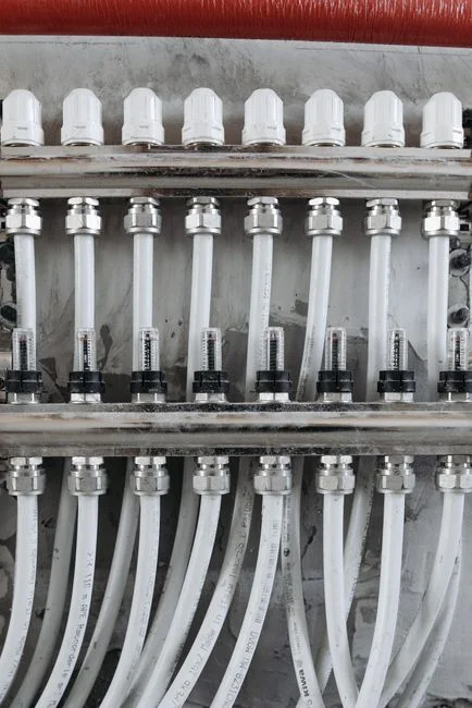
Membranes are the last item installed on site to ensure the system is fully flushed. Every upstream piece must be cleaned before any spiral-wound element is unbagged, as preservative glycerin will trap any particulate present in the line.
- Pretreatment first. Install multi-media filters that cut feed SDI to membrane-safe levels ahead of the NF skid. A properly commissioned MMF train should hold the SDI at <3 continuously, with backwash automation triggered on differential pressure (typically 7 psi across the bed) or on a timed cycle, whichever comes first.
- High-pressure pump and energy recovery before vessels. Mount and align the high-pressure pump, then pressure-test the entire piping train hydraulically at 1.5× design pressure for 30 minutes with no measurable pressure drop. This test must be witnessed and signed before any pressure vessel is loaded.
- Vessel loading. Flush the system with permeate-quality water until the drain runs clear, then load the NF elements. Each element carries a flow-direction arrow that must point toward the permeate port. Inter-element O-rings are lubricated with silicone grease only — petroleum jelly will swell EPDM and void the element warranty.
- Feed-specific configuration. Every NF system is built around the client's specification and influent water profile (Wigen Water Technologies); therefore, element count, vessel array (e.g. 2:1 for brackish, 1:1 for high-recovery), and energy-recovery selection should not be altered in the field without written engineering approval.
Wet-Out, CIP Passivation, and Membrane Conditioning
This phase determines whether the membranes survive their first year of operation. Proper chemistry ensures the system produces on spec for the full warranty term, while improper conditioning can permanently compromise the day-one flux.
- Preservative flush. Initial flush with permeate or RO-quality water (TDS < 50 mg/L), recirculating at low pressure (< 30 psi) until the drain conductivity stabilizes — typically 30–60 minutes. This step removes the sodium metabisulfite / glycerin preservation solution without shocking the membrane.
- CIP loop 1 — acid cleaner. pH 2, typically 1–2% citric or sulfamic acid, 60-minute recirculation at 30–35°C, then rinse to neutral pH (6.5–7.5). The acid pass dissolves inorganic scale and metal hydroxides accumulated during storage and shipping.
- CIP loop 2 — caustic cleaner. pH 12, typically 0.1–0.5% NaOH with a non-ionic surfactant, 60-minute recirculation at 30–35°C, then rinse to neutral pH and free chlorine < 0.1 mg/L. The caustic pass removes biological fouling and organic foulants. Polyamide NF membranes have a free chlorine tolerance of < 0.1 mg/L continuous; exceeding this during rinse is one of the most common causes of irreversible rejection loss.
- Day-zero baseline. After CIP, run a 30-minute normalized test on permeate quality and flow at the design feed pressure and reference temperature (typically 25°C). Record the values — they become the baseline certificate that the membrane manufacturer will reference if a warranty claim is filed at month 12.
| CIP Stage | Chemistry | pH | Temperature | Dwell / Recirc Time | Rinse-To Criterion |
|---|---|---|---|---|---|
| Preservative flush | Permeate / RO water | Neutral | Ambient | 30–60 min | Drain conductivity stable |
| Acid CIP | 1–2% citric or sulfamic | 2.0 ± 0.5 | 30–35°C | 60 min recirc | pH 6.5–7.5 |
| Caustic CIP | 0.1–0.5% NaOH + surfactant | 12.0 ± 0.5 | 30–35°C | 60 min recirc | pH 6.5–7.5; free Cl₂ < 0.1 mg/L |
| Day-zero baseline | Process feed at design pressure | Operating | Reference 25°C | 30 min steady-state | Recorded as warranty reference |
Performance Acceptance Test and 72-Hour Reliability Run

The performance acceptance test converts the ITP from a checklist into a contractually binding gate. These metrics match the membrane manufacturer's published specification envelope and are achievable on a clean, properly conditioned system.
- Normalized permeate flow. Within ±15% of the membrane manufacturer's design curve at 25°C reference temperature and the project's design feed pressure. Deviation greater than ±15% on day one signals either fouling, under-pressurization, or an element specification mismatch.
- Salt rejection. Within ±2 percentage points of the published spec under standard test conditions (typically 2,000 mg/L MgSO₄, 110 psi, 25°C, pH 7). For a tight NF, this reads as 95–98% MgSO₄ rejection; for a loose NF, 50–70%.
- Differential pressure per vessel. Capped at 10 psi for a clean system, with no vessel exceeding 1.2× the array average. Rising dP is the earliest fouling indicator and should be trended from day zero.
The 72-hour reliability run serves as the final contractual hand-over gate. By starting the clock only after operator training is complete and SCADA trending is verified, the supplier ensures that any failure during the run is unambiguously their responsibility. The same performance-test logic applies to industrial RO systems with recovery rates up to 95% and NF, as both are spiral-wound membrane processes governed by the same normalized-flux and rejection mathematics. A wider comparison of feed-side requirements is covered in the RO vs NF vs thermal desalination comparison.
Operator Training, Documentation, and Post-Handover Support
A system that performs on day one will regress within six months if the operations team does not inherit the technical model established during commissioning. Hand over four documents at sign-off: the as-built P&ID, the ITP signed off at every hold point, the day-zero baseline performance certificate, and an SOP covering normal start-up, normal shutdown, and the CIP trigger thresholds (typically dP rise of 15% from baseline or normalized flux decline of 10%). Train operators on the three SCADA alarms that matter: rising inter-stage dP (fouling early warning), free chlorine breakthrough (membrane damage risk), and high permeate conductivity (element integrity loss). Schedule the first membrane autopsy at 6 months for variable feed water, otherwise at 12 months. Antiscalant dosing, pH adjustment, and CIP chemical injection should be running on the same PLC-controlled automatic chemical dosing systems that were commissioned during the pre-mount window, ensuring set-point changes are auditable. For ongoing membrane care, follow the discipline of the 12-step industrial RO maintenance protocol — most of the steps transfer directly to NF.
Frequently Asked Questions
What is the single most important pre-commissioning check for an NF skid?
Feed Silt Density Index. The SDI must be <3 on a 15-minute test (ASTM D4189) before any element is loaded; an SDI above 3 will foul the membrane within hours and void the manufacturer's warranty.
What free chlorine level is safe for polyamide NF membranes?
Continuous free chlorine must stay below 0.1 mg/L. Polyamide has a free chlorine tolerance of essentially zero for long-term exposure — even brief spikes during CIP rinse-down will cause permanent rejection loss.
How long does a full CIP passivation take on a new NF skid?
Plan for 4–6 hours total: 30–60 minutes for the preservative flush, 60 minutes for the acid loop with rinse, 60 minutes for the caustic loop with rinse,