Why Mobile-Area Transportation Plants Sit Under 40 CFR 403 Pretreatment Rules
Transportation equipment plants in the Mobile industrial corridor that discharge to a sanitary sewer operate under 40 CFR Part 403, the federal General Pretreatment Regulations that govern all Industrial Users (IUs) sending wastewater to a POTW (per eCFR Title 40 Part 403). The rule does two things: it sets categorical standards for listed industries, and it forces every POTW to develop site-specific local limits under 40 CFR 403.5(c) to protect the treatment plant, its biosolids, and the receiving stream (per EPA, "Pretreatment Standards and Requirements-Local Limits").
Local limits are numeric or narrative effluent limits — including required BMPs — that the POTW writes into its sewer use ordinance and individual IU permits. They are enforced at the end-of-pipe, meaning the point of connection to the POTW collection system. For Mobile County, the controlling authority is the Mobile Area Water & Sewer System (MAWSS) operating through the MaRTrin regional collection system, and the limits you actually have to hit live in the MAWSS sewer use ordinance and your IU permit, not in the Federal Register. Permit reissuance in 2026 typically triggers a fresh industrial waste survey, a slug control plan review, and revised self-monitoring frequencies.
The two enforcement triggers EPA defines are pass-through — a pollutant that exits the POTW and causes or contributes to an NPDES violation (40 CFR 403.3(p)) — and interference — a discharge that disrupts POTW treatment or sludge processes and causes the same (40 CFR 403.3(k)). Either one can put a Mobile plant on a compliance schedule even when its own end-of-pipe numbers look fine on paper. The pretreatment train is therefore designed to make pass-through and interference effectively impossible, not just to clear a single grab sample.
The Wastewater Streams Inside a Transportation Equipment Plant
Transportation equipment manufacturing is not a single waste profile. Auto assembly, rail car, and aerospace tier suppliers each generate a different mix, and the pretreatment train is only as good as the source-stream inventory behind it. The dominant streams a Mobile-area engineer will see on a process flow diagram fall into six groups.
Parts-washer and degrease effluent carries free, emulsified, and dissolved oil and grease, plus solvent carryover and surfactant loadings that frustrate gravity separators. Metalworking fluid streams from machining cells add tramp oil, broken emulsions, dissolved Fe, Al, Cu, and Zn, COD in the 2,000–10,000 mg/L range, and biocide residuals that inhibit downstream biology. Phosphate and conversion-coating rinse water swings pH from acidic to alkaline through the rinse cascade, and carries Zn and Ni from zinc-phosphate and nickel-strike chemistries. E-coat, paint pretreatment, and clear-coat oven condensate are low-flow but troublesome: strippable organics, resin fines, and pigments that blind filters.
Boiler blowdown, cooling tower blowdown, and compressor condensate add temperature, conductivity, and intermittent oil contamination that the equalization basin must absorb. Floor wash, oil-water separator influent, and storm runoff from oily process areas produce slug loads — a 1,000-gallon spill of cutting oil or a wash-pad release that hits the pretreatment system in minutes. A defensible industrial waste survey maps every one of these streams to a flow, a pollutant envelope, and a containment story before any equipment is selected.
The 2026 Pretreatment Train: Source Control → Discharge

A defensible Mobile-area pretreatment train reads as a block flow: source control, equalization, primary separation (DAF or coalescer), chemical precipitation and pH trim, biological or membrane polish, and final monitoring. The order is not arbitrary; each step reduces the load on the next and protects the permit.
Step 1 — Source control. Dedicated collection trenches and shop-floor oil-water separators keep free oil out of the chemical waste stream. A separate sump for phosphate rinse water prevents acid spikes from killing DAF biology downstream. Step 2 — Equalization. An 8–24 hour HRT basin with mechanical or aerated mixing damps slug loads and stabilizes pH, COD, and O&G before the primary separator; a 24-hour EQ is the cheapest insurance on the entire flow sheet because it lets smaller downstream equipment do more work.
Step 3 — DAF or coalescer. A dissolved air flotation system is the workhorse: micro-bubble flotation removes 90–99% of free and emulsified oil and 80–95% of TSS in a single stage. Step 4 — pH adjustment and chemical precipitation. A PLC-controlled chemical dosing skid doses caustic or acid to keep pH inside the typical POTW 5.0–11.0 envelope, and feeds coagulant and flocculant for residual Zn, Ni, Cu, and PO₄. Step 5 — Biological or membrane polish. Add an MBR or activated-sludge stage only where the local limit demands COD/BOD reduction or where reuse is on the roadmap. Step 6 — Final polishing and monitoring. Multi-media filtration or membrane polish, UV or chlorination if disinfection is required, and a monitored sample port at the POTW connection. A GX rotary mechanical bar screen at headworks protects every downstream pump from rags and shop debris.
Design Parameters and Target Removal Efficiencies
The table below consolidates the 2026 design envelope a Mobile-area engineer can lift into a basis-of-design document. Numeric targets are quoted as ranges consistent with typical Alabama POTW local limits; actual values come from the current MAWSS sewer use ordinance and the plant's IU permit.
| Parameter | Typical end-of-pipe target | Primary removal step | Achievable removal |
|---|---|---|---|
| Oil & grease | <100 mg/L | DAF + coalescer | 90–99% |
| Total suspended solids | <250–300 mg/L | DAF (± lamella) | 80–95% |
| pH | 5.0–11.0 | Automatic acid/caustic dosing | ±0.3 SU control |
| Zinc (Zn) | Low mg/L range (per local limit) | Hydroxide precipitation at pH 9–10 | 90–99% |
| Nickel (Ni) | Low mg/L range (per local limit) | Hydroxide precipitation at pH 10–11 | 95–99% |
| Copper (Cu) | Low mg/L range (per local limit) | Hydroxide precipitation at pH 8–9 | 90–98% |
| Lead (Pb) | Low mg/L range (per local limit) | Hydroxide precipitation at pH 9–10 | 95–99% |
| Phosphate (PO₄) | Per local limit | Alum or ferric chloride precipitation | 80–95% |
| COD / BOD | Per local limit (often <300 mg/L COD) | MBR or activated sludge (if required) | 85–95% |
| Flow equalization | 8–24 h HRT | Aerated EQ basin | Smooths 5–10× slug swings |
Equalization is the cheapest line on the entire P&ID. A 24-hour basin at a 20 m³/h plant is roughly 480 m³ of wet well — modest civil work that prevents the DAF from going into a recurring chemical upset every time a parts washer dumps a batch. The online zinc monitoring sensor guide walks through how real-time metal measurement ties into this same control loop.
Equipment Selection: DAF, Lamella, MBR, or All Three?
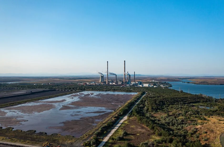
For most transportation plants, DAF is the default primary separator because oil and grease plus TSS dominate the stream. A lamella clarifier substitutes for the DAF only when TSS is consistently high (>500 mg/L) and oil loading is low — uncommon in a parts-washer-and-machining mix. If the local POTW enforces a tight COD or BOD limit, or if the plant plans to reuse effluent for rinse water or scrubber makeup, add an MBR stage using a submerged MBR bioreactor system; PVDF modules with relaxed tank geometry tolerate the surfactant residual that would otherwise upset a conventional activated-sludge tank.
For high-rate settling ahead of DAF, a high-efficiency sedimentation tank acts as a coarse grit and settleable-solids guard, reducing solids loading on the float cell and extending its service interval. pH, coagulant, and flocculant should all be on a PLC-controlled chemical dosing skid with redundant pumps and trim-loop control — manual dosing on a 24/7 unmanned line is the most common permit excursion cause. The DAF line covers 4–300 m³/h across 13 models, which brackets the typical Mobile plant envelope; MBR modules are typically selected in 5–50 m³/h standard skids.
2026 Cost Bands and Sizing Anchors for Mobile Plants
CAPEX is best expressed as a 2026 USD band per m³/h of treatment capacity so that finance can scale it to their actual flow. A DAF-only pretreatment train (EQ + DAF + chemical dosing + control skid) sits at the low end of the band, while a full DAF plus MBR train with UV polishing sits at the high end. Footprint is predictable: a packaged DAF + chemical dose + control skid for a 10–30 m³/h plant typically fits on a 30–60 m² outdoor pad with a small equipment shelter for the controls.
OPEX is dominated by coagulant and polymer consumption, sludge hauling, and aeration energy; labor is small for a PLC-controlled skid but increases once an MBR is added because of membrane cleaning and replacement. Sludge volume is the variable most permit-sensitive, and a plate-and-frame sludge filter press routinely cuts hauling cost by 60–75% versus a drying bed, which keeps the operator focused on the MAWSS septage and biosolids rules rather than the hauling bill. Actual 2026 quotes depend on influent characterization, local utility rates, and the MAWSS tariff, so treat the band as a screening tool and pull the MaRTrin sewer use ordinance before sizing the OPEX line. For peer benchmarking, the DAF vs clarifier for EV and auto parts wastewater piece is a useful cross-reference.
Permit-Readiness Checklist: Documents the POTW Will Ask For
The EHS manager can hand the following list to the MAWSS pretreatment coordinator in a single meeting. Each item maps to a specific 40 CFR 403 expectation, so the package reads as a permit reissuance package, not a question pile.
- Completed industrial waste survey: process description, block flow diagram, raw materials and chemical inventory, daily and peak flows, and pollutant envelopes per stream.
- Slug control plan: storage and secondary containment for every chemical above threshold volumes, plus worst-case release scenarios and the response chain that contains them.
- Best Management Practices (BMPs) plan: written document aligned with 40 CFR 403.5(c), covering chemical handling, floor management, and operator training.
- Monitoring plan: sample port location at the POTW connection, parameter list, sampling frequency, methods (40 CFR 136 where applicable), and lab certification.
- SPCC and stormwater cross-reference: Spill Prevention Control and Countermeasure plan tied to the facility's stormwater permit, so a single release does not trigger two enforcement cases.
- Annual report and self-monitoring records: prior-year data, excursions, corrective actions, and a forward-looking compliance schedule for any planned process changes.
Pair this package with the chemical plant pretreatment compliance guide or the fabricated metals plant pretreatment guide for sector benchmarking before the meeting.
Frequently Asked Questions
What are the typical oil and grease limits for Mobile-area POTWs?
MAWSS local limits for oil and grease are typically set at or below 100 mg/L at the point of connection, with free oil prohibited and a narrative BMP clause requiring removal by an approved interceptor or DAF. The exact number comes from the current sewer use ordinance and the plant's individual IU permit, so confirm before specifying equipment.
Does a transportation plant need a DAF or just an oil-water separator?
An API or coalescing oil-water separator handles free oil at low flow, but it cannot reliably remove emulsified oil, surfactants, or the TSS load that comes with metalworking fluids. Once a plant runs parts washers, machining coolant, or phosphate rinses, a DAF is the practical primary step because it removes free and emulsified oil plus 80–95% of TSS in a single stage.
How is a Categorical Industrial User different from a Non-Categorical IU?
A Categorical IU is subject to federal categorical pretreatment standards under 40 CFR 403.6 and 40 CFR chapter I subchapter N (for example, metal finishing at 40 CFR 433). A Non-Categorical IU has no categorical standard and is governed only by the POTW's local limits, prohibitive discharge standards under 40 CFR 403.5, and the slug control plan. Most Mobile transportation plants fall into the Non-Categorical category unless they perform explicit metal-finishing operations covered by 40 CFR 433.
What is the difference between pass-through and interference?
Pass-through (40 CFR 403.3(p)) is a pollutant that exits the POTW and causes or contributes to an NPDES permit violation. Interference (40 CFR 403.3(k)) is a discharge that disrupts the POTW's treatment processes or its sludge handling and thereby causes the same. Either one is enforceable on its own; you do not have to trigger both.
When is a Mobile plant required to install continuous pH and flow monitoring?
MAWSS typically requires continuous pH and flow recording at the monitoring point for any Significant Non-Compliance (SNC) history, categorical standards, or slug-discharge risk, with sampling per 40 CFR 136 methods. Continuous monitoring is also the easiest way to satisfy the slug control plan, because every excursion is captured on a trend record the pretreatment coordinator can review.
Can the same treatment train handle both parts-washer and paint pretreatment streams?
Yes, with source control. Keep the two streams separated at the trench, equalize them together, and let DAF handle the oil and TSS load; chemical precipitation then strips metals and phosphate. The risk is cross-contamination: a hard pH swing or a solvent slug from one stream can wipe out DAF performance for both, so the equalization basin and the slug control plan are what make combined treatment defensible.